Datasheet 85
System Management Feature Specifications
6.3 Scratch EEPROM
Also available on the SMBus interface on the processor is an EEPROM which may be used for
other data at the system vendor’s discretion (Intel will not be using the scratch EEPROM). The data
in this EEPROM, once programmed, can be write-protected by asserting the active-high SMWP
signal. This signal has a weak pull-down (10 kΩ) to allow the EEPROM to be programmed in
systems with no implementation of this signal.
6.4 Processor Information ROM and Scratch EEPROM
Supported SMBus Transactions
The processor information ROM and scratch EEPROM responds to three of the SMBus packet
types: current address read, random address read, and sequential read.
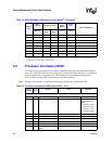
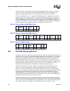
Table 6-5 shows the format of the current address read SMBus packet. The internal address counter
keeps track of the address accessed during the last read or write operation, incremented by one.
Address “roll over” during reads is from the last byte of the last eight byte page to the first byte of
the first page. “Roll over” during writes is from the last byte of the current eight byte page to the
first byte of the same page.
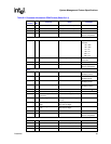
Table 6-6 shows the format of the random read SMBus packet. The write with no data loads the
address desired to be read. Sequential reads may begin with a current address read or a random
address read. After the SMBus host controller receives the data word, it responds with an
acknowledge. This will continue until the SMBus host controller responds with a negative
acknowledge and a stop.
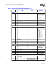
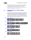
Table 6-7 shows the format of the byte write SMBus packet. The page write operates the same way
as the byte write except that the SMBus host controller does not send a stop after the first data byte
and acknowledge. The Scratch EEPROM internally increments its address. The SMBus host
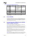
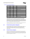
73h 32 Processor Feature Flags All other are reserved:
[4] =Upper temp reference byte
[3] =Thermal calibration offset
byte present
[2] =SCRATCH EEPROM
present
[1] =Core VID present
1 indicates EEPROM
data for specified field
is valid.
77h 4 Number of Devices in TAP
Chain
One 4-bit hex digit
78h 4 Reserved Reserved for future use 0h
79h 8 Checksum 1 byte checksum Add up by byte and
take 2’s complement.
Other
7Ah 16 Reserved Reserved for future use 0000h
NOTES:
1. Refer to the Intel
®
Itanium
®
Architecture Software Developer’s Manual for details on CPUID registers.
2. The translation is using BCD.
Table 6-4. Processor Information ROM Format (Sheet 4 of 4)
Offset/
Section
# of
Bits
Function Notes Examples


