76 Datasheet
Thermal Specifications
5.1.2 Enhanced Thermal Management
ETM is a new feature that has been added to the Itanium 2 processor. ETM uses a thermal sensing
device on the die to monitor a thermal entry point, indicating dangerous operation exceeding the
thermal specification. Once the thermal sensing device observes the temperature rise above the
thermal entry point, the processor will enter a low power mode of execution and notify the system
by sending a Correctable Machine Check Interrupt (CMCI). The Itanium 2 processor will remain in
this low power mode until the temperature decreases below the thermal entry point and remains for
approximately one second, at which point the it will send an another CMCI and resume normal
operation. If the temperature cannot be reduced and continues to rise to critical levels, the
processor will assert the THRMTRIP# signal. The ETM feature may be disabled through the PAL.
5.1.3 Thermal Trip
The Itanium 2 processor protects itself from catastrophic overheating by use of an internal thermal
sensor. The sensor trip point is set well above the normal operating temperature to ensure that there
are no false trips. The Itanium 2 processor will stop all execution when the junction temperature
exceeds a safe operating level.
Warning: Data will be lost if the Itanium 2 processor goes into thermal trip (signaled to the system by the
THRMTRIP# pin).
Once thermal trip is activated, the Itanium 2 processor remains stopped until RESET# is asserted.
The processor case temperature must drop below the specified maximum before issuing a reset to
the processor. Please see Section 5.2 for details on case temperature.
5.2 Case Temperature
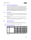
See Table 5-1 for the case temperature specifications for the Itanium 2 processor. The case
temperature is defined as the temperature measured at the center of the top surface of the IHS.
Warning: Data may be lost if the case temperature exceeds the specified maximum.
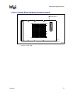
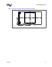
Figure 5-2 contains dimensions for the thermocouple location on the Itanium 2 processor package.
This is the recommended location for placement of a thermocouple for case temperature
measurement.
Table 5-1. Case Temperature Specification
Symbol Parameter
Core
Frequency
Minimum Maximum Unit Notes
Tcase Case Temperature 900 MHz 5 85 °C
1.0 GHz 5 85 °C
1.3 GHz 5 83 °C
1.4 GHz 5 83 °C
1.5 GHz 5 83 °C
1.6 GHz 5 83 °C
1.66 GHz 5 83 °C


