


30 Datasheet
Electrical Specifications
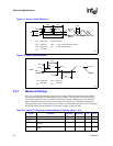
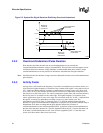
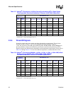
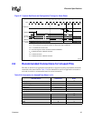
2.6 Power Pod Connector Signals
Power delivery for the Itanium 2 processor is from a DC-DC converter called the “power pod”. The
power pod consists of a DC-DC converter and a semi-flexible connector which delivers the voltage
to the processor.
Table 2-22 lists all of the signals which are part of the Itanium 2 processor power pod connector.
Warning: If the power supply cannot supply the voltages requested by the components in the Itanium 2
processor, then it must disable itself.
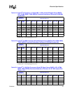
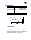
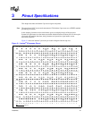
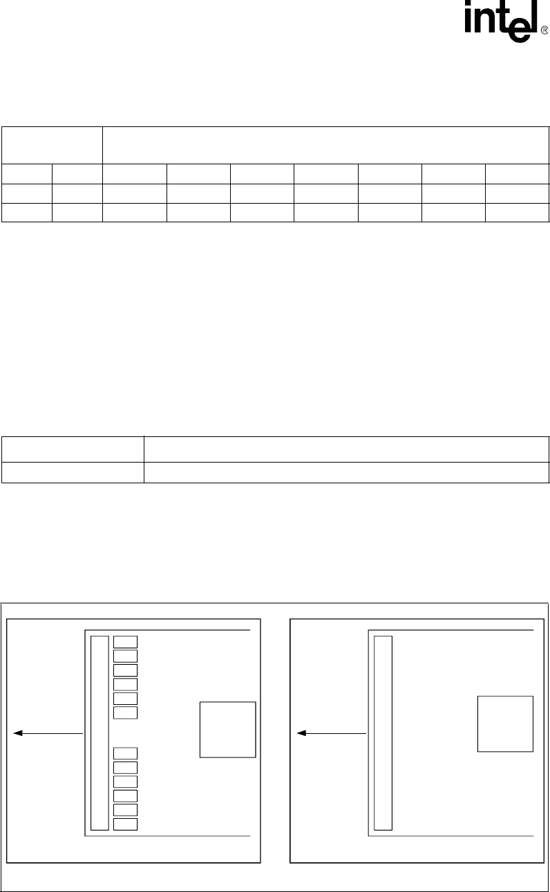
Figure 2-4 shows the top and bottom views of the power tab connector. The processor ground,
V
SS,Processor
, connection is provided on the power tab connector as well.
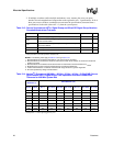
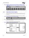
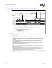
1.6 –0.4 2.4567 333333
1.55–0.353333333
1.5–0.33333333
NOTES:
1. Activity Factor = 1 means signal toggles every 6 ns.
Table 2-21. Itanium
®
2 (1.66 GHz) Processors Wired-OR Signal Group (BINIT#, HIT#, HITM#,
BNR#, TND#, BERR#) Overshoot/Undershoot Tolerance for 667 MHz System Bus
(Sheet 2 of 2)
Absolute
Maximum (V)
Pulse Duration (ns)
Table 2-22. Itanium
®
2 Processor Power Pod Connector Signals
Group Name Signals
Power Pod Connector OUTEN, CPUPRES#, PPODGD#, VCC, VCCMON, GND, VSSMON, VID[4:0]
Figure 2-4. Itanium
®
2 Processor Power Tab Physical Layout
000983a
Reserved
OUTEN
VSSMON
VCCMON
PPODGD#
CPUPRES#
Reserved
VID[4]
VID[3]
VID[2]
VID[1]
VID[0]
GND / VSS
Processor
To Power Pod
VCC
To Power Pod
Top View of Processor Bottom View of Processor
Processor
Pins