MPCBL0010 SBC—Addressing
Intel NetStructure
®
MPCBL0010 Single Board Computer
Technical Product Specification October 2006
112 Order Number: 304120
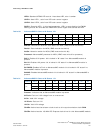
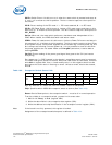
SWEv: Switch Event: this bit turns to 1 when the reset switch is pressed and stays at
‘1’ until a 1 is written at this bit position. This bit is used to capture a short pulse on
the switch.
PCIR: Direct reading of the PCI reset: 1 = PCI reset asserted; 0 = no PCI reset
PCIEv: PCI Reset Event: this bit turns to 1 when a PCI reset occurs and stays in this
state until a 1 is written at this bit position. This bit is used to capture a short pulse on
PCI_RESET.
SwHw: When set, the reset switch performs a hardware reset independent of the
IPMC. When cleared, the IPMC deals with hard/warm resets.
PFREv: Power fail reset event: this bit turns to 1 when a Power Fail occurs and stays in
this state until a 1 is written at this bit position. This bit is used to capture a short pulse
on the power source. Since power supplies are not valid during a normal power-up, this
bit is always set following a normal power-up. It is not possible to clear this bit when
the power supplies are not stable. Make sure PwrgGd (see below) is active before
clearing PFREv.
PwrGd: Directs reading of the power good signal that goes to the ICH (and resets
everything)
On a power-up (i.e. SBC inserted in the chassis), some false events may be reported.
The IPMC must ignore these first events. When the IPMC leave its reset state, its has to
write 0Ah in register 29h. Also, a "read-modify-write" on this register should not be
done since this could result in clearing an event. Unless an event need to be cleared,
write 0.
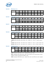
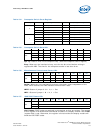
A[5..0]: Address of a VSC3108 (See the Vitesse* VSC3108 datasheet)
Chip: Specifies which VSC3108 crosspoint switch to talk to (See Table 104)
Reset: Send a Reset pulse to the crosspoint switch -- must be 0 in normal operation
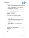
To write a nibble in a crosspoint switch, proceed in this exact order:
1. Wait for bit "Busy" to be 0 (register 2Bh).
2. Write the data nibble in the crosspoint data register (2Bh).
3. Write the address and chip identification in the crosspoint control register (2Ah).
Note: If the board is not fully powered, this register is locked.
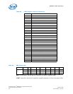
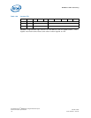
Assignment of the crosspoints switches ports is defined in Table 104:
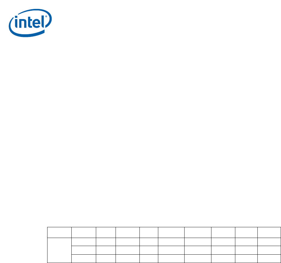
Table 103. Crosspoint Switch Control 2Ah
Address Action D7 D6 D5 D4 D3 D2 D1 D0
2Ah
Read Reset Chip A5 A4 A3 A2 A1 A0
Write Reset Chip A5 A4 A3 A2 A1 A0
PowerUp 1 0 0 0 0 0 0 0


