MPCBL0010 SBC—Feature Overview
Intel NetStructure
®
MPCBL0010 Single Board Computer
Technical Product Specification October 2006
20 Order Number: 304120
In addition to the PCI Express connections to the AdvancedMC slots, SATA and
AdvancedTCA zone 2 telecom clock signals are also connected to each AdvancedMC
slot. The MPCBL0010 SBC features a two-channel bus master PCI SATA interface
through the 6300ESB ICH. Each channel supports one device and is available through
the AdvancedMC module slots.
Each of these x8 PCI Express ports routed to the AdvancedMC connectors can train with
a link width of x8, x4, or x1. The PCI Express raw bit-rate on the data pins of 2.5 Gbit/
s results in the bandwidth per pair of 250 MBytes/s given the 8/10 encoding used to
transmit data across this interface. The result is a maximum theoretical realized
bandwidth on an x8 PCI Express port of 2 GBytes/s in each direction or an aggregate of
4 GBytes/s.
The MPCBL0010 SBC supports AdvancedMC modules with a maximum power
consumption of 20 watts for each AdvancedMC slot, and it has independent hot swap
circuitry for +12 V and +3.3 V connections.
Note: Do not operate the MPCBL0010 SBC without filler panels or AdvancedMC modules
installed. The AdvancedMC module slots should not be left open or uncovered when the
MPCBL0010 SBC is in use. The two slot filler panels included with the SBC are provided
to optimize cooling and radiated emissions for the SBC.
Note: Shipping the MPCBL0010 SBC with third party AdvancedMC modules installed may
cause damage to the SBC or AdvancedMCs. Shipping damage that occurs to the
MPCBL0010 SBC due to AdvancedMC modules installed during shipment may not be
covered by the SBC product warranty.
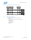
2.2.6 Firmware Hubs
The MPCBL0010 SBC supports two 8 Mbit (1 MByte) BIOS flash ROMs (Firmware
Hubs):
•Primary BIOS flash ROM (FWH0)
• Recovery BIOS flash ROM (FWH1)
The flash is allocated for BIOS and firmware use.
The SBC boots from the primary flash ROM under normal circumstances. During the
boot process, if the BIOS (or IPMC) determines that the contents of the primary flash
ROM are corrupted, a hardware mechanismautomatically changes the flash device
select logic to the recovery flash ROM and restarts the boot process.
Each flash component has a separately write-protected boot block that prevents
erasure when the device is upgraded.
Flash ROM BIOS updates can be performed by an end user locally, or a network
administrator over the LAN via telnet. The SBC should have a local copy of the flash
update utility and the BIOS data files, or have the capability to copy the flash update
utility and BIOS data files onto a local drive from the network. The flash update utility
has a command line interface to specify the path and the file name of the BIOS data
files. After completing the BIOS ROM update, users should shutdown and reset the SBC
for the new BIOS ROM to take effect.
2.2.6.1 FWH0 (Main BIOS)
The BIOS executes code off of the flash ROM and performs checksum validation of its
operational code. This checksum occurs in the BIOS boot block. The BIOS image is also
stored in FWH0 firmware hub. During a BIOS update, the BIOS image is stored in FWH0
only. FWH0 also stores the factory default CMOS settings and user-configured CMOS
settings.


