Intel NetStructure
®
MPCBL0010 Single Board Computer
October 2006 Technical Product Specification
Order Number: 304120 97
Addressing—MPCBL0010 SBC
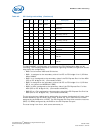
Note: POST codes are not always 16-bit and the high byte in register 81h could be unrelated
to the content of register 80h. Also, only a 16-bit Write to I/O 80h will write to I/O
81h. An 8-bit Write to I/O 81h is ignored.
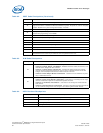
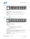
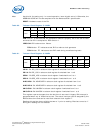
Version: Programmable logic version.
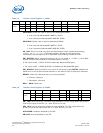
EnHD: Setting this bit uses LED Amber0 for displaying hard disk activity.
EnPost: Enables using the debug LED to display the last POST code of the boot. The
BIOS clears this bit prior to the operating system launch.
EnClk: Enables telecom clock monitoring on the debug LED. EnHD and EnPost must be
cleared. When the LED is green, both clocks are present. When the LED is amber, only
one clock is present. When the LED is red, no clock is present or the Telco Clock PLD is
not initialized. This is a debug mode.
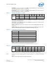
Green0/Red0/Amber0: Debug LED 0. Used as a debug LED or to display POST codes
(default during boot) or hard disk activity (default following boot) or as an end-user
status/debug LED.
RJ45: This bit tells the FPGA which LEDs should reflect LAN activity; RJ-45 LEDs or
grouped LEDs. The BIOS should set this bit as soon as possible to reflect the
configuration of the fabric LAN. This should be set to 0 if the LAN goes to the fabric.
MfgFlag: A memory element used by the BIOS and test software in manufacturing.
Note: Tthis bit is cleared on a power-up, but is not affected by a reset
The Debug LED is amber/green when in Reset (this is hardware). As soon as the FPGA
is programmed, the LED is amber and is enabled for POST code display. If the BIOS
fails, it is possible to read the POST code. If the BIOS succeeds, it disables the POST
code and enables HD activity on the green LED. If needed, the application software can
then disable hard disk activity reporting and directly control the bi-color LED for status
reporting.
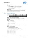
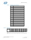
To read the 8-bit POST code:
• Both colors: Start of POST sequence.
• Amber blink: This is the high nibble. 0 to 15 blinks represent hexadecimal 0 to F.
• Green blink: This is the low nibble. 0 to 15 blinks represent hexadecimal 0 to F.
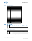
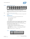
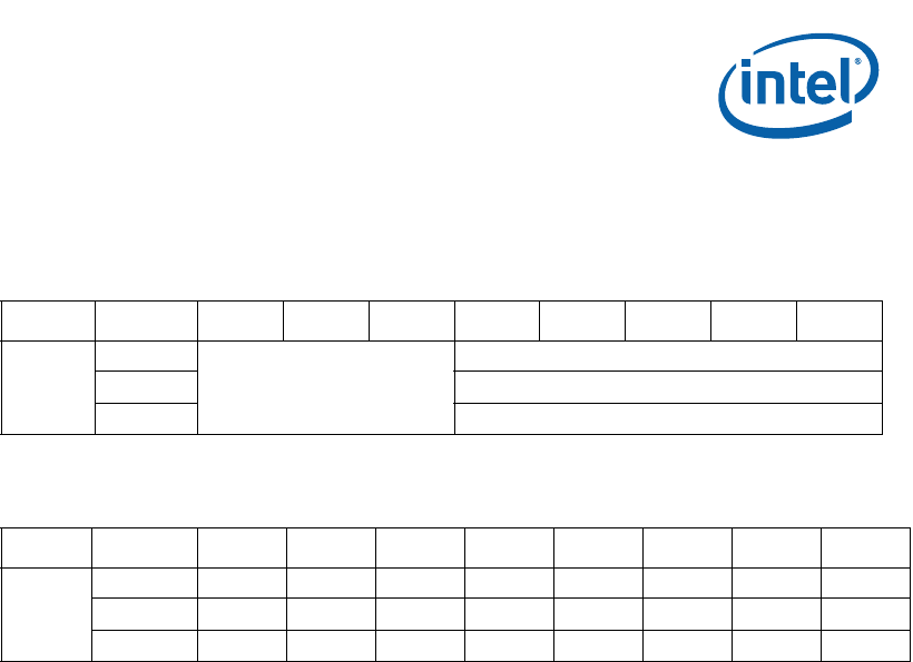
Table 70. FPGA Version 0A00h
AddressActionD7D6D5D4D3D2D1D0
0xA00
Read
Reserved
Version
Write NU
Reset Version
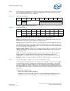
Table 71. Debug LED 0A01h
AddressActionD7D6D5D4D3D2D1D0
0xA01
Read MfgFlag RJ45 EnHD EnPost EnClk Green0 Amber0 Red0
Write MfgFlag RJ45 EnHD EnPost EnClk Green0 Amber0 Red0
Reset0/NA1010000


