


Technical Reference 103
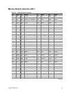
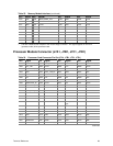
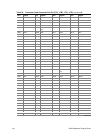
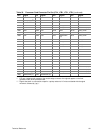
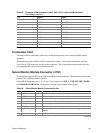
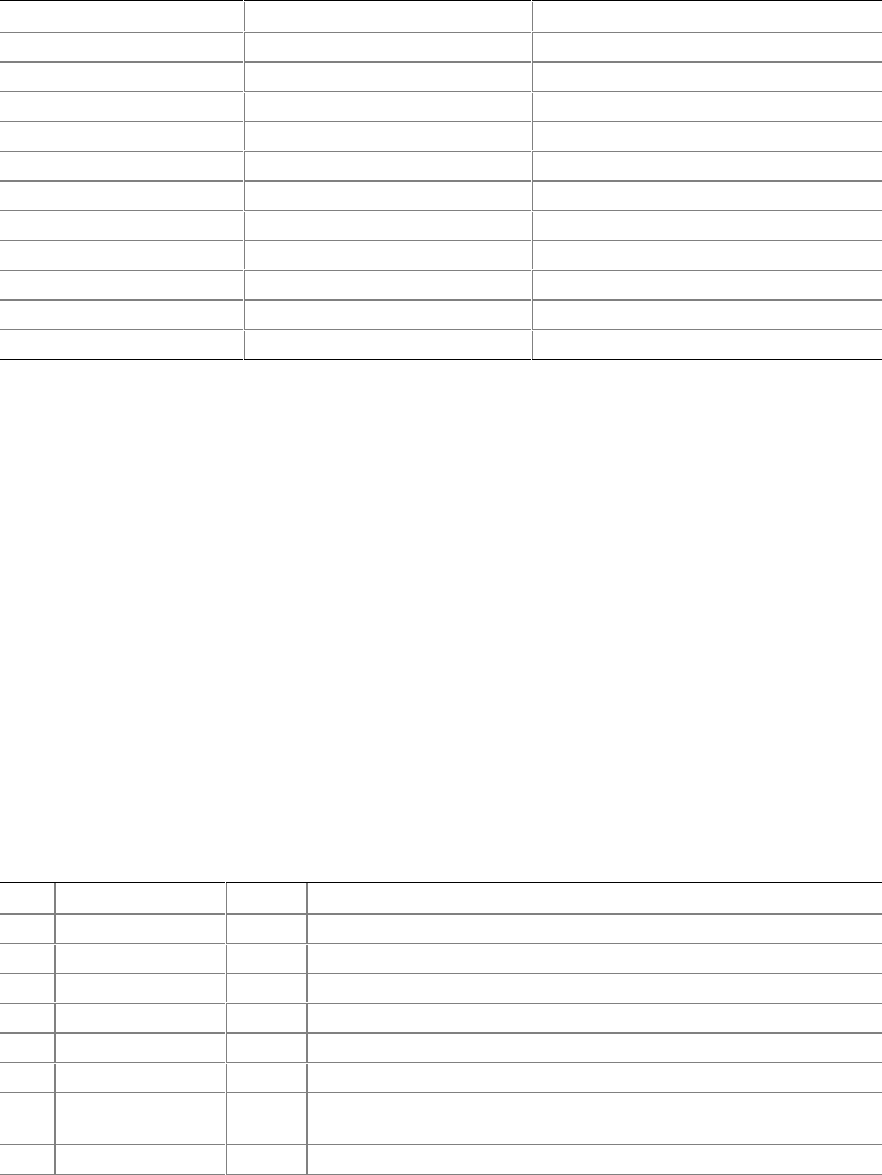
Table 55. Processor VRM Connectors (J2A2, J2B1, J2C1): Add-in VRM Connector
Pin Listing (continued)
Pin Signal Type*
B10 VSS6 POWER
B11 VCCP7 POWER
B12 VSS7 POWER
B13 VCCP8 POWER
B14 VSS8 POWER
B15 VCCP9 POWER
B16 VSS9 POWER
B17 VCCP10 POWER
B18 VSS10 POWER
B19 VCCP11 POWER
B20 VSS11 POWER
* Type (in/out) is from the perspective of the baseboard.
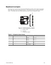
Termination Card
You must install a termination card in any vacant processor card slot to ensure reliable system
operation.
The termination card contains AGTL+ termination circuitry, clock signal termination, and Test
Access Port (TAP) bypassing for the vacant connector.
The system does not boot unless all slots
are occupied with a processor or termination card.
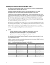
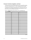
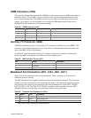
Server Monitor Module Connector (J7H1)
The baseboard supports the Server Monitor Module feature connector.
The table below shows the
pinout of the 26-pin baseboard connector.
On the SKA4 baseboard, pins 1, 9, 15, and 17 are connected to SMI_L, NMI, SECURE_MODE,
and CHASSIS_INTRUSION. Some server systems do not monitor these signals.
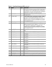
Table 56. Server Monitor Module Connector Pin Out
Pin Signal Type* Description—SKA4 Implementation
1 SMI_L out System Management Interrupt:
not supported on SMM
2 I2C_SCL in I
2
C clock line
3 CONP_L out Connector Present:
tied to ground on the baseboard
4 Reserved Reserved pin:
NC on baseboard
5 PWR_CNTL_L in Power supply on/off control:
allows SMM to control system power
6 I2C_SDA in/out I
2
C serial data line
7 5VSTNDBY out +5 V standby:
monitored by SMM to determine if AC power is
applied
8 Reserved Pulled up to 5 V through 10k on baseboard
continued