


Removing and Installing Baseboard Components 61
Memory
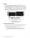
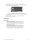
Memory amounts from 256 MB to 16 GB of DIMM are supported, with a 64/72-bit
four-way-interleaved pathway to main memory, which is also located on the module. Therefore,
data transfers between MADPs and DIMMs is in four-way interleave fashion. Each of the four
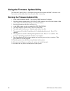
DIMMs must be populated in a bank. The 16 slots are divided into four banks of four slots each.
They are labeled A through D. Bank A contains DIMM sockets A1, A2, A3, and A4. Banks B, C,
and D each contain 4 DIMM sockets and are named in the same fashion. There are silk screens on
the module next to each DIMM socket to label its bank number. DIMM banks do not have to be
filled in any order, but for best thermal results, you should populate them from A to D. If only one
DIMM bank is used, use bank A first, and then B, C, and D.
OM09919
A1
A2
A3
A4
B1
B2
B3 B4
C1
C2
C3
C4
D1
D2
D3
D4
XY
Z
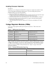
Figure 3. Memory Module DIMM Installation Sequence
X. One of sixteen DIMM sockets
Y. One of four Memory Address Data Paths (MADP)
Z. Memory Expansion Card Connector (MECC)
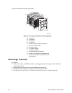
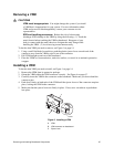
Removing the Memory Module
See “Memory” on page 16 for memory size and requirements. The memory module is located on
the baseboard as shown in Figure 1 on page 14. The DIMM locations are shown in Figure 3.
1. Observe the safety and ESD precautions at the beginning of this chapter.
2. Remove the memory module from the baseboard:
• Pull the module upward slightly to disengage it from the baseboard connector.
• Slide the module straight up and away from the baseboard until it clears the guide rails.
• Place the module component-side up on a nonconductive, static-free surface.