


110 SKA4 Baseboard Product Guide
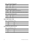
Password Clear Jumper
The jumper at pins 5, 6, and 7 controls whether a stored password is retained or cleared during a
system reset.
Procedure to clear the current password and then enter a new one:
1. Observe the safety and ESD precautions at the beginning of this procedure.
2. Turn off all connected peripherals, turn off system power, and disconnect all AC power cords.
3. If the baseboard is installed in a system, remove access covers so that you have access to the
baseboard.
4. Remove the memory module. See "Removing the Memory Module" on page 61.
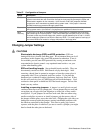
5. Locate the configuration jumpers at the edge of the baseboard next to the memory expansion
card connector (MECC).
6. Move the Password jumper from pins 5 and 6 to pins 6 and 7.
7. If the baseboard is installed in a system, reinstall the access covers, connect the power cords,
and turn on the system for the change to take effect.
8. Wait for POST to complete and for the message
Press F1 to resume, Press F2 to Setup
to be displayed.
9. Turn off the system, and disconnect all AC power cords from the system.
10. Move the jumper from pins 6 and 7 back to pins 5 and 6.
11. If the baseboard is installed in a system, reinstall the access covers, connect the power cords,
and turn on the system for the change to take effect.
12. Run BIOS Setup or the SSU to specify a new password. See Chapter 3.
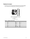
Recovery Boot Jumper
The jumper at pins 9, 10, and 11 controls whether the system attempts to boot using the BIOS
programmed in flash memory.
Procedure to disable recovery booting:
1. Observe the safety and ESD precautions at the beginning of this procedure.
2. Turn off all connected peripherals, turn off system power, and disconnect all AC power cords.
3. If the baseboard is installed in a system, remove access covers so that you have access to the
baseboard.
4. Remove the memory module. See "Removing the Memory Module" on page 61.
5. Locate the configuration jumpers at the edge of the baseboard next to the memory expansion
card connector (MECC).
6. Move the recovery boot jumper from pins 9 and 10 to pins 10 and 11.
7. If the baseboard is installed in a system, reinstall the access covers, connect the power cords,
and turn on the system for the change to take effect.
8. Turn the system on, and insert the Flash Memory Update Utility diskette in drive A. After the
system boots, the recovery process starts. This takes about three minutes. When the recovery
process completes, the speaker emits two beeps.