


14 SKA4 Baseboard Product Guide
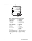
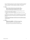
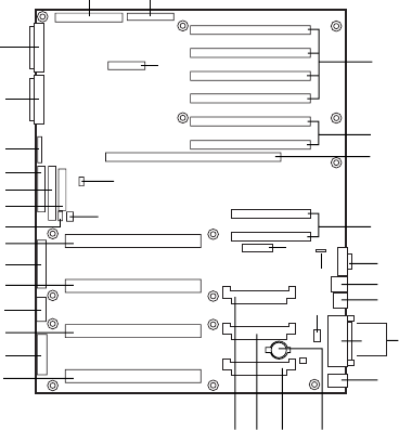
Baseboard Connector and Component Locations
A B
J
JJ
I I
HH
K
M
N
O
G
H
F
P
I
GG
FFEE
DD
Q
CC
R
BB
S
AA
E
D
T
U
V
W
X
Y
Z
C
L
OM09918
Figure 1. Baseboard Connector and Component Locations
A. Legacy Narrow SCSI B. Legacy Wide SCSI
C. SMM Connector D. IMB Connector
E. HDD Activity F. HPIB Connector
G. ICMB Connector H. Internal USB Connector
I. Lithium Battery J. Memory Module Connector
K. Video Connector L. USB, External Connector
M. Network Connector N. Parallel Connector
O. COM1, COM2 Connector P. Keyboard/Mouse
Q. Main Power 1 R. Auxiliary Power
S. Main Power 2 T. SMBus
U. Front Panel V. IDE Connector
W. Floppy Connector X. Configuration Jumpers
Y. Ultra 160 SCSI A Z. Ultra 160 SCSI BA. Legacy
Narrow SCSI
AA. Processor #1 BB. Processor #2
CC. Processor #3 DD. Processor #4
EE. Voltage Regulator Module (VRM)
Connector #2
FF. Voltage Regulator Module (VRM)
Connector #3
GG. Voltage Regulator Module (VRM)
Connector #4
HH. 32-bit, 33 MHz Half-length PCI
Slots
II. 64-bit, 66/33 MHz Hot-Plug PCI
Slots
JJ. 64-bit, 33 MHz Hot-Plug PCI Slots