


Removing and Installing Baseboard Components 69
Note the location of the lithium battery in Figure 1 on page 14.
1. Observe the safety and ESD precautions at the beginning of this chapter and the additional
warning given on page 68.
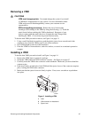
2. Remove the VRMs in VRM connectors 3 and 4. For more information, see "Removing a
VRM" on page 67.
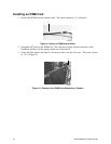
3. Insert the tip of a small flat-bladed screwdriver or equivalent under the plastic tab on the
snap-on plastic retainer.
4. Gently push down on the screwdriver to lift the battery.
5. Remove the battery from its socket.
6. Dispose of the battery according to local ordinance.
7. Remove the new lithium battery from its package and, being careful to observe the correct
polarity, insert it in the battery socket.
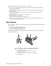
Add-in Boards
Figure 1 on page 14 identifies the add-in board locations. The SKA4 baseboard contains eight PCI
slots. There are
• Two 32-bit, 33 MHz half-length PCI slots
• Two 64-bit, 66/33 MHz Hot-Plug PCI slots
• Four 64-bit, 33 MHz Hot-Plug PCI slots
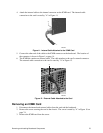
Typically, the Hot-Plug PCI add-in boards are held in the Hot-Plug slots by a front and rear Hot-
Plug retention mechanism.
B
A
OM09943
C
D
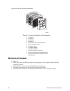
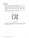
Figure 7. Example of a Front Hot-Plug Retention Mechanism
A. Green and Amber LEDs
B. Press here on the inside of the chassis and then rotate to
release the PCI board
C. PHP Retention Mechanism from the outside of the chassis
D. HW push-button