


104 SKA4 Baseboard Product Guide
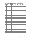
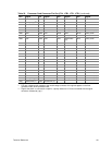
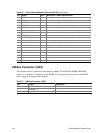
Table 56. Server Monitor Module Connector Pin Out (continued)
Pin Signal Type* Description—SKA4 Implementation
9 NMI out Non-maskable interrupt:
not supported on SMM
10 HOST_AUX out Baseboard voltage monitored by SMM card:
connected to 3.3 V
11 RESET_L in Baseboard reset signal from Server Monitor Module
12 GROUND ground Ground
13 GROUND ground Ground
14 Key No connect on baseboard
15 SECURE_MODE out Secure mode indication:
not supported on SMM
16 GROUND ground Ground
17 CHASSIS_INTRUSION out Chassis intrusion indication:
not supported on SMM
18 Reserved Reserved pin:
NC on baseboard
19 Reserved Reserved pin:
NC on baseboard
20 GROUND ground Ground
21 Reserved Reserved pin:
NC on baseboard
22 Reserved Reserved pin:
NC on baseboard
23 Reserved Reserved pin:
NC on baseboard
24 Reserved Reserved pin:
NC on baseboard
25 key No connect on baseboard
26 Reserved Reserved pin:
NC on baseboard
* Type (in/out) is from the perspective of the baseboard.
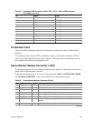
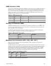
SM Bus Connector (J9E4)
This connector allows connection to the Memory Module I
2
C bus that the DIMMs EEPROMs
reside on. A shorted I
2
C connection at the SM Bus I
2
C connector will prevent the system BIOS
from sizing and configuring main memory.
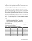
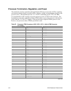
Table 57. SM Bus Connector (J9E4)
Pin Signal Description
1 Local I2C SDA OSB4 SM Bus Data Line
2 GROUND
3 Local I2C SCL OSB4 SM Bus Clock Line