


ZT8101 User’s Manual 35
Switch Management and Operating Concepts
Additional IP Interfaces
To add an IP interface to the switch, you must first configure a VLAN and then associate an IP
address (subnet mask and gateway) with the VLAN. These user-defined IP interfaces differ from
the System IP interface in the following ways:
• They cannot use BOOTP/DHCP to get a dynamic IP address. They must be assigned a manual
IP address.
• They can be renamed. However, when the change is applied, all other settings for the IP
interface are changed to their default values. This includes the settings for RIP and the IP
multicast protocols.
IP Addressing Scheme
An IP addressing scheme must be established and implemented when the IP interfaces are set up on
the switch.
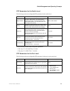
For example:
In this case, six IP interfaces (or six subnets) are required, so a CIDR notation of 10.32.0.0/11 (or a
11-bit) addressing scheme will work. This addressing scheme will give a subnet mask of
11111111.11100000.00000000.00000000 (binary) or 255.224.0.0 (decimal).
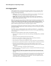
A10.xxx.xxx.xxx IP address notation provide six network addresses. For example:
The six IP interfaces, each with an IP address listed in the table above and a subnet mask of
255.224.0.0, can be entered into the Setup IP Interface form.
IP interfaces consist of two parts—a subnet mask and an IP address.
Each IP interface listed above provides a maximum of 2,097,150 unique IP addresses per interface
(assuming the 10.xxx.xxx.xxx notation).
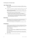
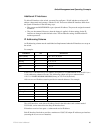
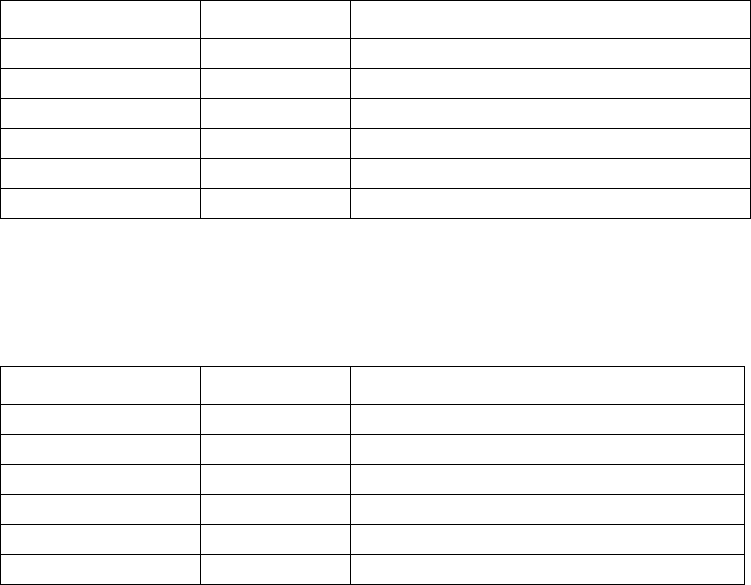
VLAN Name VID Switch Ports
System (default) 1 5, 6, 7, 8, 21, 22, 23, 24
Engineering 2 9, 10, 11, 12
Marketing 3 13, 14, 15, 16
Finance 4 17, 18, 19, 20
Sales 5 1, 2, 3, 4
Backbone 6 25, 26
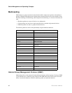
VLAN Name VID Network Address
System (default) 1 10.32.0.0
Engineering 2 10.64.0.0
Marketing 3 10.96.0.0
Finance 4 10.128.0.0
Sales 5 10.160.0.0
Backbone 6 10.192.0.0