


12. Protective functions
12-5 SV-iC5
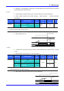
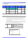
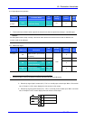
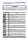
12.4 Output phase loss protection
Group LED display Parameter Name
Set
value
Min/Max
setting
Factory
default
Unit
Function
group 2
H19
[Output phase loss
protection select]
1
0/1
0
Set H19 value to 1.
This function turns off the inverter output in the event of more than one phase loss among U, V and W output.
Caution :
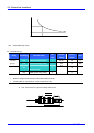
Set H33- [Motor rated current] correctly. If the actual motor rated current and the value of H33 are different, this
function could not be activated.
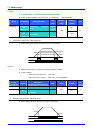
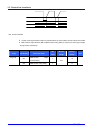
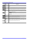
12.5 External trip signal
Group LED display Description
Set
Value
Min/Max
setting
Factory
default
Unit
I20
[Multi-function input terminal
P1 define]
0
~ ~
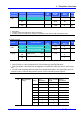
I23
[Multi-function input
terminal P4 define]
18
3
I/O group
I24
[Multi-function input
terminal P5 define]
19
0/24
4
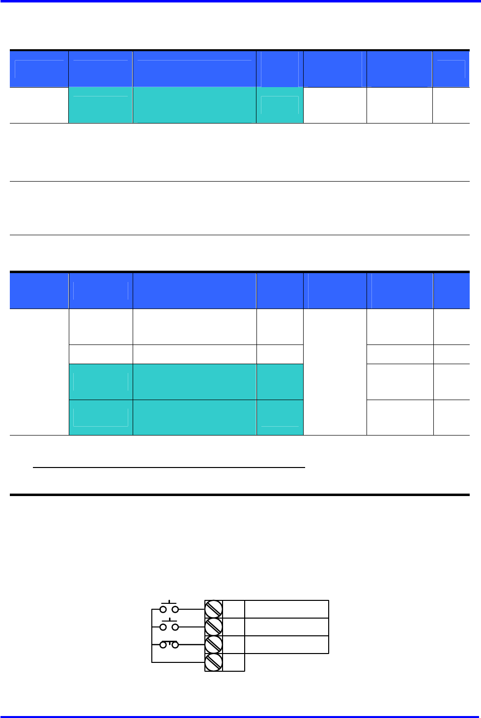
Select a terminal among P1 thru P5 to output external trip signal.
Set I23 and I24 to 18 and 19 to define P4 and P5 as External A contact and B contact.
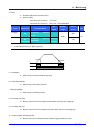
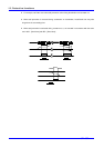
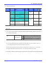
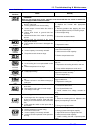
External trip signal input A contact (N.O) : This is a normally open contact input. When a P4 terminal
set to “Ext trip-A” is ON, inverter displays the fault and turns off its output.
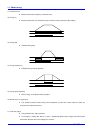
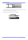
External trip signal input B contact (N.C) : This is a normally closed contact input. When a terminal
set to “Ext trip-B” is OFF, inverter displays the fault and turns off its output.