


7. Function list
7-16 SV-iC5
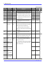
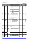
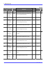
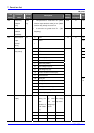
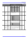
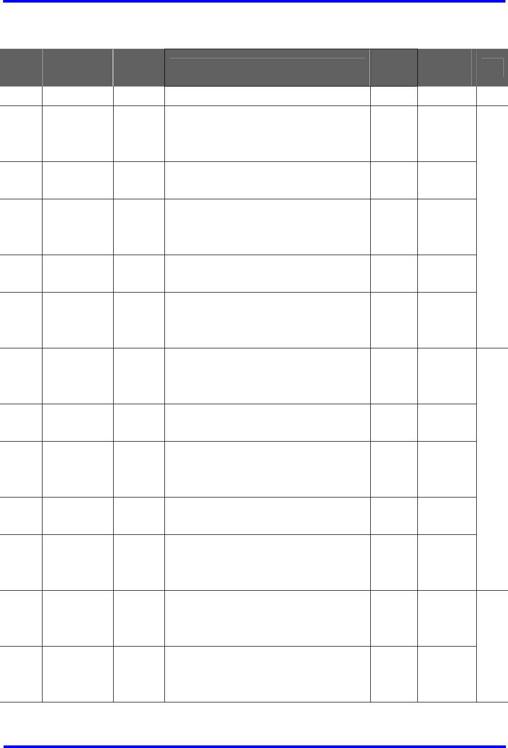
I/O group
LED
display
Parameter
name
Min/Max
range
Description
Factory
defaults
Adjustable
during run
Page
I 0 [Jump code] 0/63 This parameter sets the code number to jump 1 O 5-5
I 1 [Filter time
constant for
V0 input]
0/9999 This is used to adjust the analog voltage input
signal via keypad potentiometer.
10 O
I 2 [V0 input Min
voltage]
0/10
[V]
Set the minimum voltage of the V0 input. 0 O
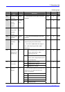
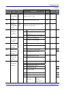
I 3 [Frequency
corresponding
to I 2 ]
0/400
[Hz]
Set the inverter output minimum frequency at
minimum voltage of the V0 input.
0.0 O
I 4 [V0 input Max
voltage]
0/10
[V]
Set the maximum voltage of the V0 input. 10 O
I 5 [Frequency
corresponding
to I 4]
0/400
[Hz]
Set the inverter output maximum frequency at
maximum voltage of the V0 input.
60.0 O
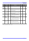
9-2
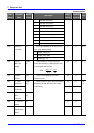
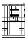
I 6 [Filter time
constant for
V1 input]
0/9999 Set the input section’s internal filter constant for
V1 input.
10 O
I 7 [V1 input Min
voltage]
0/10
[V]
Set the minimum voltage of the V1 input. 0 O
I 8 [Frequency
corresponding
to I 7]
0/400
[Hz]
Set the inverter output minimum frequency at
minimum voltage of the V1 input.
0.0 O
I 9 [V1 input max
voltage]
0/10
[V]
Set the maximum voltage of the V1 input. 10 O
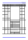
I10 [Frequency
corresponding
to I 9]
0/400
[Hz]
Set the inverter output maximum frequency at
maximum voltage of the V1 input.
60.0 O
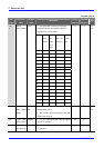
9-3
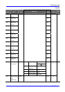
I11 [Filter time
constant for I
input]
0/9999 Set the input section’s internal filter constant for
I input.
10 O
I12 [I input
minimum
current]
0/20
[mA]
Set the Minimum Current of I input. 4 O
9-4