


9. Basic functions
9-3 SV-iC5
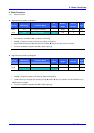
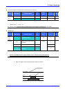
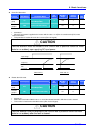
Analog Frequency setting via Voltage analog input (0-10V) or potentiometer on the VR terminal
Group LED Display Parameter Name
Set
Value
Min/Max
Range
Factory
Defaults
Unit
0.0 [Frequency command] - - - Hz
Drive
group
Frq [Frequency mode] 3
0/8 0
I 6 [Filtering time constant for V1 input] 10 0/9999 10
I 7 [V1 input minimum voltage] - 0/10 0 V
I 8 [Frequency corresponding to I 7] - 0/400 0.0 Hz
I 9 [V1 input max voltage] - 0/10 10 V
I/O group
I10 [Frequency corresponding to I 9] - 0/400 60.0 Hz
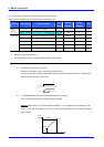
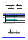
Select Frq -[Frequency Mode] to 3 {Frequency setting via V1 terminal}.
The 0-10V input can be directly applied from an external controller or a potentiometer (between VR and CM
terminals).
Wire the terminal as shown below and refer to page 9-2 for I 6 - I10.
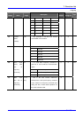
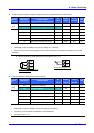
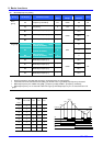
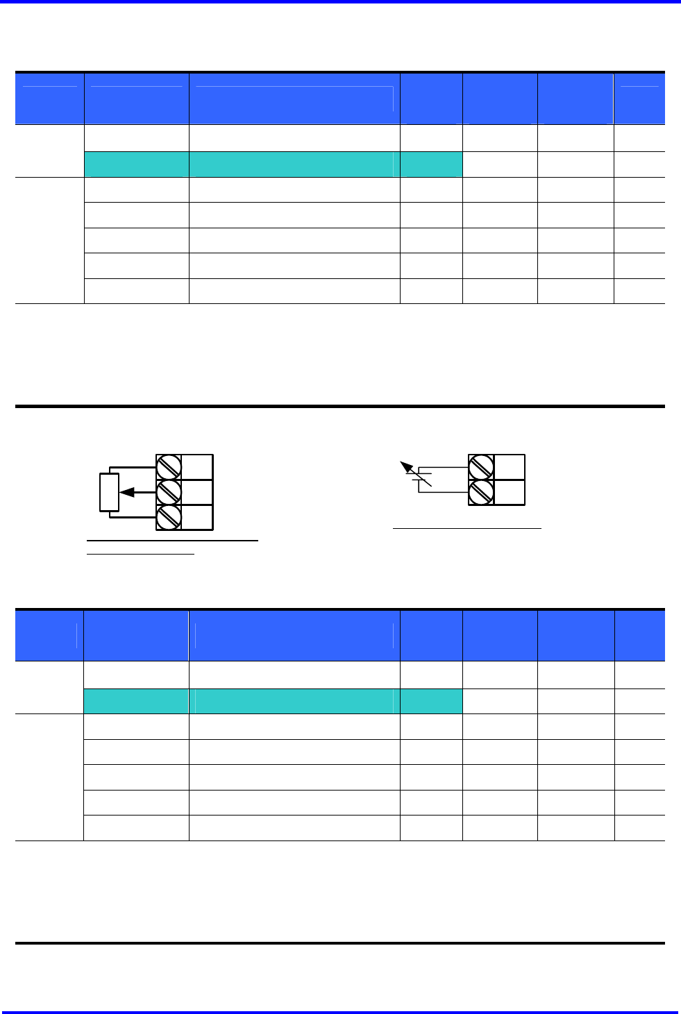
Frequency Setting via Analog Current Input (0-20mA)
Group LED Display Parameter Name
Set
Value
Min/Max
Range
Factory
Defaults
Unit
0.0 [Frequency Command] - - - Hz
Drive
group
Frq [Frequency Mode] 4
0/8 0
I11 [Filtering time constant for I input] 10 0/9999 10
I12 [I input minimum current] - 0/20 4 mA
I13 [Frequency corresponding to I 12] - 0/400 0.0 Hz
I14 [I input max current] - 0/20 20 mA
I/O group
I15 [Frequency corresponding to I 14] - 0/400 60.0 Hz
Select Frq – [Frequency Mode] to 4 {Current Analog Input (0-20mA)}.
Frequency is set via 0-20mA input between I and CM terminals.
See page 9-2 for I11-I15.
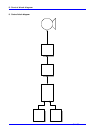
VR
V1
CM
When connecting potentiometer to
terminals VR and CM
V1
CM
Analog Voltage Input (0-10V)