


• EPS 6000 battery cabinet
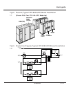
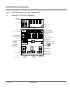
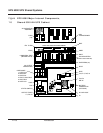
Each of these cabinets is described below. Figure 1-1 shows a typical shared UPS
installation, consisting of one static switch cabinet (SSC), two UPS modules, and two adjacent
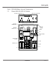
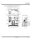
battery cabinets. Figure 1-2 shows a single-line diagram of the same
shared UPS installation. Table 1-1 identifies EPS 6000 UPS model numbers for modules
used in shared systems, and Table 1-2 identifies EPS 6000 SSC model numbers.
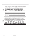
Table EPS 6000 Model Numbers, Shared System UPS Modules
1-1
Table
EPS 6000 Model Numbers, Static Switch Cabinets (SSC)
1-2
LEDOM
REBMUN
TUPNI
EGATLOV
)CAV(
TUPTUO
EGATLOV
)CAV(
TUPTUO
GNITAR
Wk/AVk
BCTUPNI
)serepmA(
LATOT
HTDIW
)ni/mm(
LATOT
THGIEW
)bl/gk(
TAEH
SSOL
)rh/utB(
0051CSS0840840021/0051000227/92810092/7131)elbigilgeN(
LEDOM
REBMUN
TUPNI
EGATLOV
)CAV(
TUPTUO
EGATLOV
)CAV(
TUPTUO
GNITAR
)Wk/AVk(
BCTUPNI
)spmA(
HTDIWLATOT
)ni/mm(
LATOT
THGIEW )bl/gk(
TAEH
SSOL
)rh/utB(
P66,44/0516-SPE084084021/0510045.18/010,2805,4/440,2818,03
P66,44/5226-SPE084084081/5220045.18/010,2805,4/440,2202,93
-SPEP66,44/0036084084042/0030065.18/010,2345,5/415,2962,25
P66,44/5736-SPE084084003/5730075.18/010,2216,5/545,2633,56
P66,44/0056-SPE084084004/0050001311/568,2112,7/442,4354,97
6-SPEP66,44/057084084006/0570061591/009,42,31/000,600,131000
:SETON
.1 .stellapgnidulcxetubstenibacyrailixuagnidulcnipu-enilmetsysroferassoltaehdna,thgiew,htdiwlatoT
.2 .tnempiuqeruoyhtiwdeilppussgniwardnoitallatsniehtotrefer;atadyrettabedulcnitonseodataD
.3 ehttlusnoC.tnempiuqelanoitpohtiwegnahcyamatad;snoitarugifnocdradnatsrofsidedivorpnoitamrofnI
.tnempiuqeruoyhtiwdedivorpsgniwardnoitallatsni
1 — 2 Introduction
EPS 6000 UPS Shared Systems