


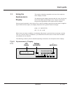
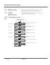

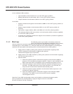

To display battery voltage, current, ambient temperature,
and time available or remaining, press the battery key on
the keyboard, as shown in Figure 2-25.
Figure Battery Measurements
2-25
This section presents normal operating procedures for the
EPS 6000 UPS.
It is best to contact MGE Customer Support Services
for start-up and maintenance of the EPS 6000 UPS. Do not allow unqualified personnel
to operate the EPS 6000.
Before starting the EPS 6000 UPS, make certain that these
conditions exist (as applicable to your installation):
• All power and control wires have been properly connected and securely tightened.
• The upstream and downstream protective devices are not tripped, and have been
sized properly for the UPS and load requirements.
• The voltage at each main AC input circuit breaker Q1 and at the bypass input
circuit breaker Q4S is the same as indicated on the UPS nameplate, located inside
the right door of the EPS 6000 UPS module.
• The air filters located inside each EPS 6000 UPS module front door are properly
installed and free of dust, dirt, and debris. Make certain that no objects block the
air intake at the front bottom of the enclosures, and that the air exhaust at the top
rear of the enclosures is free of obstructions.
2.4.1 Checks Before
Start-up
2.4 Normal Operating
Procedures
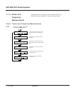
Select battery measurements by
pressing the "battery" pushbutton.
UBAT.
V
AVAILABLE BAT.TIME
MN %KV LOAD =
IBAT.
* A
T BAT.
°
C
OR
REMAINING BAT. TIME
MN %KV LOAD =
ı
ı
ı
ı
Baattery voltage (VDC), charge (+) or discharge
(–) current (ADC), and battery temperature
(degrees Celsius).
If the main input (main 1) source is available, this
indicates the amount of battery time (in minutes)
available in the event of a main input outage.
If the main input (mains 1) source is out of
tolerance or is unavailable, this indicates the
amount of battery time (in minutes) remaining for
on-battery operation.
2 — 29Operation
User’s guide