


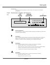

Forced bypass to inverter (pushbutton #4) (applies to SSC only)
Pressing and holding the “security key” while pressing this pushbutton forces the
transfer of the load to the inverter output when the bypass is out of tolerance.
Enough UPS modules must have been started; press the “inverter on” pushbutton
on their front panels if necessary. The load will experience a 0.8 second inter-
ruption. Refer to Section 2.4.2, Start-up, and Section 2.4.6, Forced Transfers.
Forced inverter to bypass (pushbutton #5) (applies to UPS module only)
Pressing and holding the “security key” while pressing this pushbutton stops the
inverter and disconnects the module from the load, even if the bypass is out of
tolerance; if all UPS modules are stopped, the load will be transferred to
bypass with a 0.8 second interruption. Refer to Section 2.4.6, Forced Transfers.
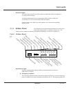
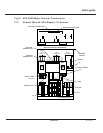
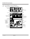
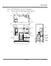
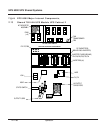
EPS 6000 circuit breakers and switches (except the
battery disconnect circuit breaker QF1) are located behind
the doors of the UPS cabinet, or through the door in the
optional MBC. Following is a brief description of the
available circuit breakers, contactors and switches, and
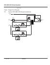
their function. The single-line diagram in Figure 2-9
shows the location of each circuit breaker, contactor and switch within the electrical path,
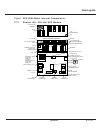
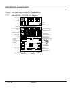
and Figure 2-10 thorugh Figure 2-17 show the location of each switch, contactor and circuit
breaker within the enclosures.
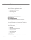
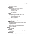
Upstream of the SSC:
Q4S Customer-supplied upstream circuit breaker, used to isolate the SSC from the bypass AC
input (mains 2) source and provide backfeed protection.
In the SSC (and optional MBC):
Q2S Wrap-around circuit breaker (automatic), used to supply the attached load via the bypass
AC input (mains 2) source.
Q3BP (Optional), system maintenance bypass circuit breaker, used to supply the attached load
via the maintenance bypass source while the SSC is being serviced.
Q5N (Optional), system isolation circuit breaker, used to isolate the shared system from the
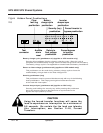
2.2.4 Circuit Breakers,
Contactors and
Switches
Using the forced transfer functions will cause the
load to experience an interruption for a minimum of
0.8 seconds. Be certain the the load can tolerate
this interruption; see Section 2.4.6, Forced
Transfers.
CAUTION
2 — 13Operation
User’s guide