


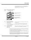

To isolate the SSC for maintenance, or to transfer the load
to maintenance bypass input source (if present), follow the
procedure that applies to your configuration.
This procedure assumes that the UPS system is
operating normally, with the attached load supplied
via the UPS modules.
1. Isolate all the UPS modules by following the procedure in Section 2.4.5.1.
2. Open the upstream bypass circuit breaker Q4S.
The whole UPS system is now isolated for maintenance. For complete protection, Q4S or the
upstream circuit breaker supplying Q4S should be locked open and tagged while the UPS
system is being serviced.
To restart the UPS system after maintenance:
1. Close the upstream bypass circuit breaker Q4S. After about 10 seconds, the
wrap-around circuit breaker Q2S will close and supply the attached load
via the bypass source.
2. Restart the UPS modules by following the procedure in Section 2.4.5.1.
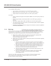
This procedure assumes that the UPS system is
operating normally, with the attached load supplied
via the UPS modules:
1. Isolate all the UPS modules by following the procedure in Section 2.4.5.1.
2. Close the system maintenance bypass circuit breaker Q3BP.
3. Open the system isolation circuit breaker Q5N. The SSC is now isolated from
the load, which is supplied by the maintenance bypass AC input source.
4. Open the upstream bypass circuit breaker Q4S.
2.4.5.2.2
With Maintenance
Bypass
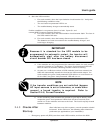
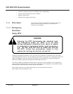
Opening Q4S with the UPS modules off in a UPS
system with no maintenance bypass will disconnect
the attached load.
CAUTION
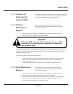
2.4.5.2.1
Without
Maintenance
Bypass
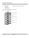
2.4.5.2 Isolation of
Static Switch
Cabinet (SSC)
2 — 35Operation
User’s guide