The whole UPS system is now isolated for maintenance. For complete protection,
Q4S or the upstream circuit breaker supplying Q4S should be locked open and
tagged while the UPS is being serviced.
To restart the UPS system after maintenance:
1. Close the upstream bypass circuit breaker Q4S. After about 10 seconds, the wrap-
around circuit breaker Q2S will close.
2. Close the system isolation circuit breaker Q5N.
3. Open the system maintenance bypass circuit breaker Q3BP. The SSC is now on
line and the load is supplied via the bypass source.
4. Restart the UPS modules by following the procedure in Section 2.4.5.1.
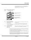
This section describes the normal transfer conditions
and the procedures to be followed when
issuing forced transfers.
To transfer the load between the UPS module output and
the bypass AC input (mains 2) source without interruption,
the following conditions must be satisfied:
• UPS module output and bypass AC input phases must be in sync
• Bypass AC input voltage must be within 10% of nominal
• Bypass AC input frequency must be within a certain
programmable tolerance of nominal
Provided that both the UPS module output and bypass AC input sources meet these
conditions, uninterrupted transfers can take place. If these conditions are not met, transfers
cannot take place without interruption. A forced transfer is required.
Forced transfers require a power interruption to the load of 0.8 seconds. Before issuing a
forced transfer command, be certain that the attached load can tolerate the brief outage.
The following paragraphs describe the forced transfer procedures.
2.4.6.1 Uninterrupted
Transfer Conditions
Using the forced transfer functions will cause the
load to experience an interruption for a minimum of
0.8 seconds. Be certain the the load can tolerate
this interruption.
CAUTION
2.4.6 Forced Transfers
2 — 36 Operation
EPS 6000 UPS Shared Systems


