


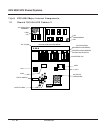
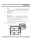
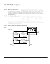

During normal operation (as shown in Figure 2-1), power
flows from the main AC input source (mains 1) into the UPS
rectifier/battery charger sections. The rectifier/battery chargers convert the AC voltage to DC,
maintain the charge on the batteries, and feed the DC power to the inverters. The inverters
regenerate AC voltage, and supply the SSC’s UPS module AC output bus. The SSC supplies
the attached load.
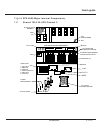
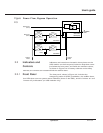
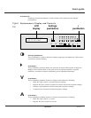
If the main AC input source (mains 1) fails or goes out of
tolerance, the chargers stop. Power flows from the batteries
to the UPS inverters, which in turn supply the attached load (as shown in Figure 2-2). When
the main AC input source (mains 1) returns, the chargers restart automatically and the UPS
system resumes its normal operation (as shown in Figure 2-1).
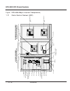
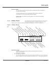
If the batteries become depleted before the main AC input source (mains 1) returns, the
inverters stop and the attached load is transferred to the bypass AC input source (mains 2) if it
is available (as shown in Figure 2-3).
Figure Power Flow, On-Battery Operation
2-2
TO
ATTACHED
LOAD
Main AC input
(mains 1)
Rectifier/battery
charger
Inverter
Battery
Rectifier/battery
charger
Inverter
Battery
UPS module
UPS module
Static switch
cabinet (SSC)
Additional
modules
Additional
modules
Bypass AC input
(mains 2)
Q2S
Static switch
2.1.3 On-Battery Operation
2.1.2 Normal Operation
2 — 2 Operation
EPS 6000 UPS Shared Systems