


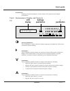

J: Inverter desynchronized
This orange LED indicates that the inverter output frequency is not synchronized
with the bypass AC input (mains 2).
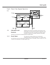
K: Transfer fault
This red LED indicates a transfer fault, which may be one or
more of the following conditions:
• Inverter output contactor K3N fault
• Current sharing relay fault
• Static switch power supply fault
• Transfer control board fault
• Power supply board fault
L: Overload
This orange LED indicates an alarm condition resulting from one
or more of the following conditions:
• UPS module inverter current above rating
• UPS module output current above rating
• SSC output current above rating
• UPS module and/or SSC shutdown due to excessive load current
M: Bypass AC input (mains 2) outside tolerance
This orange LED indicates that the bypass AC input (mains 2) voltage and/or
frequency are too high or too low.
N: Maintenance position
This orange LED indicates that circuit breakers QF1, Q4S, Q5N, or Q3BP
are set to the maintenance position. The UPS module or SSC is
not available for load protection.
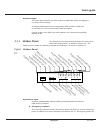
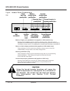
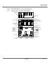
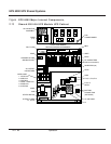
Test connector (Figure 2-8)
This 9-pin connector is reserved for service. It is used to connect
the cabinet to a computer, allowing system calibration, personalization,
and computer-aided diagnostics.
Pushbuttons
Following are brief descriptions of the function of the hidden panel pushbuttons,
shown in Figure 2-8.
Clear fault log
Pressing this pushbutton clears the alarms stored in memory, allowing the unit to
restart. Memorized alarms cannot be cleared until the condition causing the alarm
has been corrected.
Audible alarm reset
Pressing this pushbutton stops the audible alarm. Should a new fault condition at
a higher alarm level occur, the alarm will sound again.
2 — 11Operation
User’s guide