


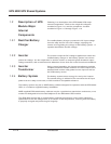
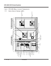

The static switch cabinet (SSC) provides an electrical path
between the output of the UPS modules and the load.
When the UPS modules are off, the SSC provides power to
the load from the bypass AC input source (mains 2). Up to
six (6) modules can be connected to the SSC, supporting
loads as great as 1,500 kVA. UPS modules may be turned
off individually for maintenance, provided that the remaining modules can support the load.
The SSC incorporates a static bypass switch. A wrap-around circuit breaker (Q2S) in the SSC
switches between the UPS module output and the bypass AC input source (when the UPS
modules are off). Optionally, the SSC can be provided with its own maintenance bypass
cabinet (MBC), allowing the SSC and/or any attached UPS module to be serviced while the
load is supplied via the maintenance bypass AC input source.
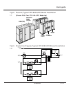
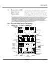
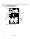
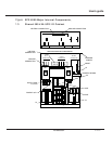
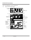
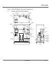
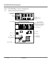
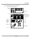
Figure EPS 6000 Major Internal Components,
1-3 Shared 150 - 225 kVA UPS Modules
FRONT VIEW, DOORS AND COVERS REMOVED
TOP VIEW, COVER REMOVED
INVERTERS
OUTPUT
CIRCUIT BREAKER
NEUTRAL CONNECTION
(BEHIND OUTPUT)
OUTPUT XFMR
(BEHIND BREAKERS)
RAUZ PCA
DC CAPACITORS
OUTPUT FUSES F7, F8, F9
120V AC OUTLET
(FOR MGE USE ONLY)
(BEHIND EACH INVERTER)
OBEZ PCA
IBEZ PCA
FAN
TRANSFORMER
FB9
1- GTCZ PCA
2- SRIZ PCA
3- CRIZ PCA
4- CROZ / DO6Z PCA
5- AROZ PCA
6- ALEZ PCA
CARD CAGE:
ALBZ
CHARGER, STATIC SW,
INPUT
CONNECTIONS
GROUND
CONNECTIONS
BATTERY
CONNECTIONS
OUTPUT
CONNECTIONS
K3N
1
C3B3A3
BAIZ & TREZ
(BEHIND PLATE)
EPOZ
INPUT FUSES F1, F2, F3
FUSES F16, F17
F18, F19
FB1 TO FB8
F10,F11 RATED 2A,500VDC
F12,F13
AC CAPACITOR
ASSEMBLY
FANS
(x 6)
6543
1 2
FB4
FB3
FB2FB1
FB8
FB7
FB6FB5
C4B4A4
+
2
3
4
5
6
INVERTER FUSES (BEHIND)
Q1 Q5N
ARUZ PCA (BEHIND MTG. PLATE)
ACPZ PCA
APOZ PCA
K3NZ PCA
1.3 Description of SSC
Major Internal
Components
1 — 5Introduction
User’s guide