


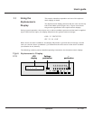


The LCD can display comprehensive information about
UPS performance through its monitoring functions.
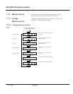
To display voltage measurements, press the “V” key on the
keyboard, as shown in Figure 2-22.
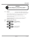
Figure Voltage Measurements
2-22
Select voltage measurements by
pressing the
◊ pushbutton
INPUT VAB VBC VCA
V RMS
BYPASS VAN VBN VCN
V RMS
BYPASS VAB VBC VCA
V RMS
INV. VAN VBN VCN
V RMS
INV. VAB VBC VCA
V RMS
LOAD VAN VBN VCN
V RMS
LOAD VAB VBC VCA
V RMS
◊
◊
◊
◊
◊
◊
◊
◊
Main input (mains 1) phase-to-phase voltages
in VAC RMS.
Bypass input (mains 2) phase-to-neutral
voltages in VAC RMS.
Bypass input (mains 2) phase-to- phase
voltages in VAC RMS.
Inverter output phase-to-neutral voltages in
VAC RMS.
Inverter output phase-to-phase voltages in
VAC RMS.
Load phase-to-neutral voltages in VAC RMS.
Load phase-to-phase voltages in VAC RMS.
(Only in UPS modules)
(only in SSC)
(only in SSC)
(only in UPS modules)
(only in UPS modules)
2.3.3.1 Voltage
Measurements
2.3.3 Measurements
2 — 26 Operation
EPS 6000 UPS Shared Systems