


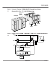
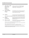
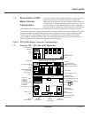
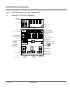
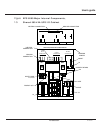
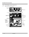
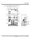
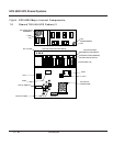
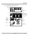

Following is a description of the EPS 6000 UPS major
internal components. Refer to the single-line diagram
provided in Figure 1-2, and the component locators
provided in Figure 1-3 through Figure 1-10
The rectifier/battery charger converts the AC input voltage
from the utility source into a DC voltage, supplying the
inverter and regulating the charge of the battery system. A
capacitor bank filters the DC voltage.
The inverter chops the DC voltage supplied from either the
rectifier/battery charger or the battery system into a three-
phase AC voltage. An AC output filter is used to achieve a computer-grade sinewave output
voltage waveform, with a total harmonic distortion of less than 2% under linear-load conditions.
During normal operation, the inverter transformer provides
complete electrical isolation between the UPS output to the
attached load and the utility power source input as well as
the UPS battery source.
The battery system stores energy for use by the inverter.
The stored energy is utilized in the event that the AC input
power from the utility source fails, or falls outside of acceptable tolerance.
The battery system may be an MGE battery cabinet designed for operation with the EPS 6000
UPS, or a customer-supplied battery installation.
MGE-supplied EPS 6000 battery cabinets may be a provided as stand-alone enclosures, or as
enclosures designed to be mounted adjacent to the EPS 6000 UPS module.
The EPS 6000 comes with a special battery ambient temperature sensor which allows the
optimization of the DC voltage level as a function of the temperature, ensuring that the battery
is properly charged and preserving its longevity.
1.2.4 Battery System
1.2.3 Inverter
Transformer
1.2.2 Inverter
1.2.1 Rectifier/Battery
Charger
1.2 Description of UPS
Module Major
Internal
Components
1 — 4 Introduction
EPS 6000 UPS Shared Systems