


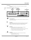
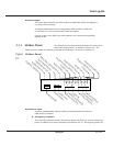
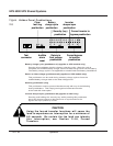
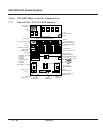

Figure Hidden Panel Pushbuttons
2-8
Battery charge cycle (pushbutton #1) (applies to UPS module only)
Pressing this pushbutton begins a battery charging cycle. After the cycle is
complete, the rectifier/battery charger returns to float charge levels on the battery.
The battery charge cycle is not applicable to sealed lead-acid battery installations.
Return to float voltage (pushbutton #2) (applies to UPS module only)
This pushbutton can be used during a battery charge cycle to force the
rectifier/battery charger back to the float voltage level.
Security pushbutton (key)
This pushbutton must be pressed simultaneously with any of the following
three pushbuttons. This helps guard against inadvertent transfer
of the load with interruption.
Inverter desync/sync (pushbutton #3) (applies to SSC only)
Pressing and holding the “security key” while pressing this pushbutton
forces the inverter output to desynchronize or synchronize to the
bypass AC input (mains 2) source.
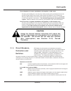
Using the forced transfer functions will cause the
load to experience an interruption for a minimum of
0.8 seconds. Be certain the the load can tolerate
this interruption; see Section 2.4.6, Forced
Transfers.
CAUTION
Test
connector
Clear
fault log
pushbutton
Audible
alarm
reset
Battery
charge cycle
pushbutton
Return to
float voltage
pushbutton
Security (key)
pushbutton
Inverter
desync/sync
pushbutton
Forced bypass
to inverter
pushbutton
Forced inverter to
bypass pushbutton
NMLKJIHGFEDCBA
12 345fault
2 — 12 Operation
EPS 6000 UPS Shared Systems