


This section presents operating information for EPS 6000
UPS shared systems, including an overview of the system,
its components, and their function; a description of the indicators and controls and their
function; and operational sequences to be followed for all conditions of normal, emergency,
and maintenance operation.
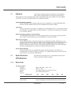
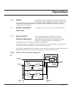
This section presents an overview of system operation.
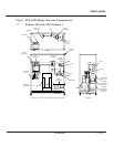
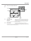
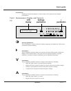
During normal operation (as shown in Figure 2-1),
and on-battery operation (shown in Figure 2-2), the
attached load is supplied by the UPS modules through
the SSC. The SSC maintains synchronization of
the UPS modules, and monitors their proper performance.
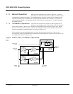
If all UPS modules have stopped, for instance during an overload condition or maintenance,
the attached load is supplied by the SSC’s bypass input source.
If the SSC is equipped with the maintenance bypass option, the load may still be supplied with
power while the SSC is serviced, via the maintenance bypass AC input source.
Figure Power Flow, Normal Operation
2-1
TO
ATTACHED
LOAD
Main AC input
(mains 1)
Rectifier/battery
charger
Inverter
Battery
Rectifier/battery
charger
Inverter
Battery
UPS module
UPS module
Static switch
cabinet (SSC)
Additional
modules
Additional
modules
Bypass AC input
(mains 2)
Q2S
Static switch
2.1.1 Static Switch
Cabinet Operation
2.1 System Operation
Overview
2.0 Scope
2 — 1
Operation