


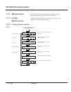


2. Open the UPS isolation circuit breaker Q5N.
3. Open the battery disconnect circuit breaker(s) QF1.
4. Open the input isolation circuit breaker Q1.
The UPS module is now isolated for maintenance. For complete protection, the upstream
circuit breaker supplying the UPS module should be opened, locked, and tagged while the
UPS is being serviced.
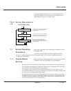
To restart the UPS module after maintenance:
1. Close the input isolation circuit breaker Q1.
2. Close the isolation circuit breaker Q5N. The UPS module fans will start.
3. Wait for the green LED “B” on the hidden panel to turn on (indicating that the
rectifier/battery charger has started), then close the battery disconnect circuit
breaker QF1. If there is more than one battery cabinet in your configuration, close
all the battery disconnect circuit breakers.
4. If the module is not programmed for automatic restart, start the inverter by
pressing the “inverter on” pushbutton on the UPS front panel. In a few moments,
the inverter will start and the UPS module will resume normal operation.
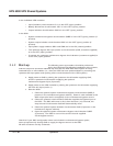
If the transfer conditions are not satisfied (bypass out of tolerance or other reason),
a forced transfer will be required. Refer to Section 2.4.2, Start-up, and
Section 2.4.6, Forced Transfers.
Because it is standard for the UPS module to be
programmed for automatic restart, the inverter will
automatically start after the battery disconnect
circuit breaker QF1 has been closed.
IMPORTANT
When one UPS module in a shared system is shut
down, it may cause the remaining modules to enter
an overload or current-limiting condition, if they
are unable to fully support the attached load. The
remaining modules may shut down after a certain
time or immediately (depending on the load level),
and the load may be transferred to the bypass AC
input source.
IMPORTANT
2 — 34 Operation
EPS 6000 UPS Shared Systems