


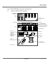
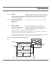
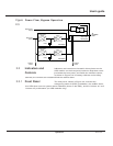
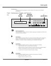

Figure Power Flow, Bypass Operation
2-3
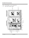
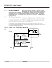
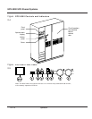
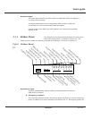
Indicators and controls are located in three places on the
UPS module: on the front panel, behind a drop-down cover
just below the front panel, and inside the enclosure doors,
as shown in Figure 2-4. In battery cabinets and auxiliary
cabinets, the controls are located behind the cabinet doors.
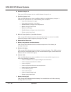
The front panel, shown in Figure 2-5, includes the
emergency power off (EPO) pushbutton, the audible alarm,
four LEDs that serve as system status indicators (three on the SSC), and the “inverter on” and
“inverter off” pushbuttons (on UPS modules only).
2.2.1 Front Panel
2.2 Indicators and
Controls
TO
ATTACHED
LOAD
Main AC input
(mains 1)
Rectifier/battery
charger
Inverter
Battery
Rectifier/battery
charger
Inverter
Battery
UPS module
UPS module
Static switch
cabinet (SSC)
Additional
modules
Additional
modules
Bypass AC input
(mains 2)
Q2S
Static switch
2 — 3Operation
User’s guide