


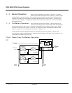
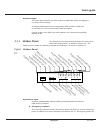

Numbered lights
The green light indicates the UPS module or SSC with which the display is
currently communicating.
A red light indicates that the corresponding UPS module or SSC has
an anomaly or is not communicating with the display.
Light #1 refers to the SSC; the UPS modules are numbered sequentially
starting at #2.
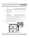
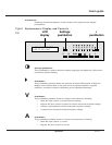
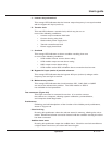
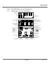
The hidden panel is located directly below the front panel,
behind the hinged cover, as shown in Figure 2-4. The
hidden panel includes the following controls and indicators, as shown in Figure 2-7:
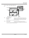
Figure Hidden Panel
2-7
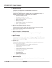
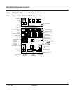
Alphabetical lights
Fourteen alphabetically labeled LEDs provide detailed information on
UPS status as follows:
A: Emergency shutdown
This red LED indicates that the emergency power off (EPO) or remote emergency
power off (REPO) has been activated (see Section 2.4.4.1, Emergency power off).
T
est connector
Clear faults
Alarm reset
Battery charge cycle
Return to float voltage
Security
Inverter sync/desync
Forced transfer
Forced shutdown
Emergency shutdown
Rectifier/charger on
Rectifier/charger fault
Input outside tolerance
Battery temp. outside tolerance
Battery charging
Inverter fault
Low batt. shutdown imminent
Inverter desynchronized
T
ransfer fault
Overload
Bypass outside tolerance
Maintenance position
NMLKJIHGFEDCBA
12 345
fault
2.2.3 Hidden Panel
2 — 9Operation
User’s guide