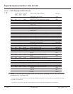
See Figure 2-1 on page 2-2 for the location of indicators and
controls.
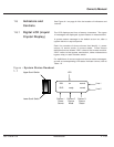
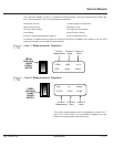
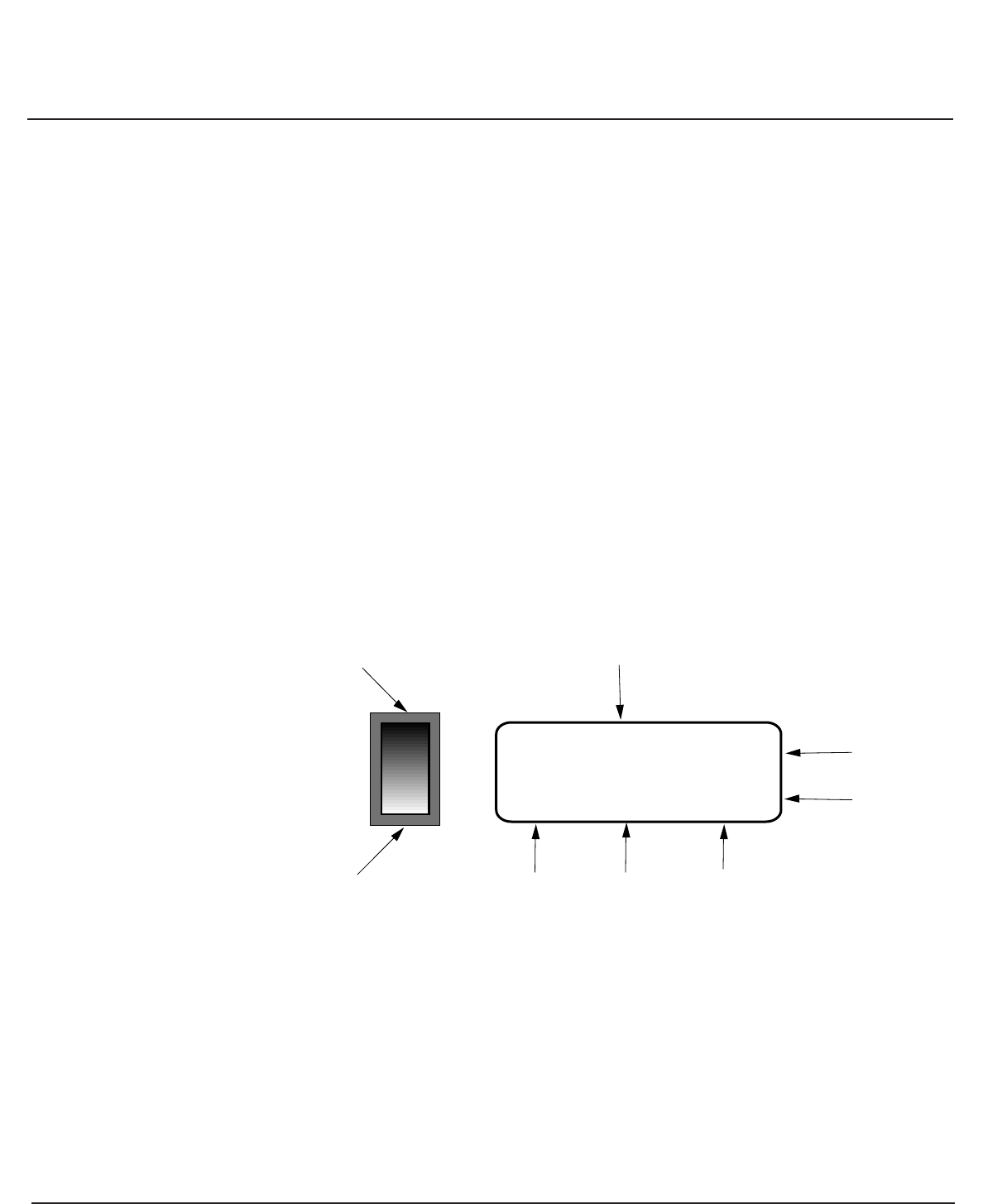
The LCD displays two lines of twenty characters. Two types
of messages are displayed: system status or measurement.
A system status message is the default at turn-on, after a
system failure or stop sequence.
Each line consists of three columns that identify: 1) power
source, 2) source mode, 3) source status. Power source
definitions are as follows: "INV." refers to the inverter module.
"BYP" refers to the bypass mechanism, either maintenance
bypass relay or static transfer switch.
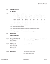
For definitions of source mode and source status messages,
as well as corresponding LED status indicator colors, refer to
Table 1-2 .
Figure : System Status Readout
1- 1
INV: on normal
BYP: ready normal
Upper Scroll Switch
Lower Scroll Switch
Column 1
Power
Source
Column 2
Source
Mode
Column 3
Source
Status
LCD
Line 1
Line 2
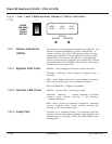
1.6.1 Digital LCD (Liquid
Crystal Display)
1.6 Indicators and
Controls
86-153061-00 1 — 5Introduction
Owner’s Manual


