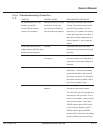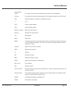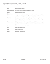
Table :Troubleshooting Checklist
4- 2
SYMPTOM POSSIBLE CAUSE RECOMMENDED PROCEDURE
No response when DC circuit Polarity reversed on DC Input Check input connections and reverse
breaker is turned ON. connections. If this is the if wrong. Remove the inverter module
Inverter STATUS indicator case, the internal Soft Start from the receiver cabinet. The soft
remains non-illuminated fuse will need to be replaced. start fuse (F1) is located in an opening
on the right hand side of the module. A
spare fuse has been supplied with this
manual. Replace F1 and re-install the
module.
Inverter start up but STATUS Overload. Connect the load directly to the AC
indicator goes to RED after lamp power source and measure the current
test start-up load sequence. and watts.
Incorrect Inverter output voltage Disconnect load. Turn system ON. Use
or frequency. the meter function on the front panel or
multimeter to check output voltage and
frequency.
Wrong input voltage. Check input source and system
specification. If Inverter was powered
up with the 230 VAC on the input and
the Inverter was set for 120, damage to
the Inverter module is possible. Return
the unit to the depot for repair.
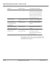
Maintenance Bypass relay Turn off the DC circuit breaker on the
defective. front panel of the inverter module.
Turn off the AC input circuit breaker and
disconnect the AC input wires. Turn on
the DC circuit breaker on the front panel
of the inverter module. If the inverter
STATUS indicator goes to RED, return
inverter module to depot for repair. If
STATUS indicator goes to GREEN,
inverter is OK. Verify that no AC voltage
(less than 5VAC) exist on the AC input
86-153061-00 4 — 7Maintenance and Service
Owner’s Manual


