


When the inverter is enabled (by turning ON the front panel
DC circuit breaker) the microprocessor goes through its start
up sequence, including phase locking the reference sine
wave to the Utility AC input. Then the maintenance bypass
relay is energized, opening its contacts. The inverter is
turned ON to check its functional operation, then turned back
OFF. The Inverter output relay is closed , Inverter enabled
and the Static Transfer Switch (SCRs) are turned OFF. This
sequence is accomplished without any break (less than 1
millisecond) in output voltage to the load. If a severe
overload should occur, the static transfer switch (SCRs) will
be turned back ON and the Inverter disabled until the
overload is removed. For overloads greater than 150%, the
maintenance bypass relay will be de-energized, effectively
shorting out the SCRs. Other overloads and failure of the
Inverter will also cause transfer to the bypass mode. The DIP
switch accessible through a opening in the side of the
Inverter module must be set to the proper position to achieve
this mode of operation.
This mode allows the load to be powered at all times from the
Utility power source through the Static Transfer Switch. The
maintenance Bypass relay will be energized (contacts open).
When the DC circuit breaker (on the front panel) is turned
ON, the inverter will go through a sequence similar to that
defined above, except the Inverter will not be powering the
load. Transfer to the Inverter will occur only if the Utility
voltage fails to be within specified limits (-20% to +10%). The
STATUS indicator will blink indicating the inverter status. The
DIP switch located on the side of the Inverter module must
be set to the proper position to obtain this mode of operation.
Advantage of OFF LINE mode is that the system is more
efficient. Only a small amount of power is required by the
Inverters electronics (less than 30 watts).
The digital LCD has two lines of 20 characters. A "SCROLL"
switch allows scrolling through the display messages which
include as a minimum: Utility voltage and utility frequency
(only with static transfer switch), output voltage , output
current, output frequency, input DC voltage, input DC
current, percent load. All of this data is supplied to the LCD
from the microprocessor.
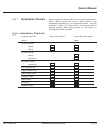
Two LEDs are on the front panel identified as "STATUS". The
left most LED is for "BYPASS" status and the right LED is for
"INVERTER" status.
3.1.5 Status Indicators
(LEDs)
3.1.4 Digital LCD Display
3.1.3.2 Off-Line Mode
3.1.3.1.2 Start Up Sequence
3 — 8 Theory of Operation 86-153061-00
Topaz S3 Inverters 0.5 kVA, 1 kVA, & 2 kVA