


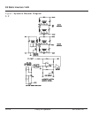

The duty cycle of the UC3842ANs oscillator is set up to be
about 45%. The output of the chip drives the gate of an
IRF840 FET. The "Drain" of the FET is connected to a
"Flyback" transformer (actually a coupled inductor of 50 uHy
primary inductance). At the beginning of the switching cycle,
the FET is turned ON. Current starts to build up linearly in
the primary of this inductor. A resistor located in the
"Source" lead of the FET is used to measure the current in
the primary of the transformer. This signal is applied to the
UC3842ANs current sense port. When this voltage (current
in the transformer's primary) reaches the correct level as
determined by the chip’s voltage error amplifier output, the
FET is turned OFF. Now the energy stored in the "Flyback"
transformer is transferred into the output capacitors.
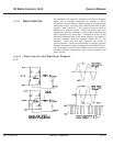
Remember! Energy (Watt -seconds) times the number of
energy bundles per second is equal to Watts. If the
transformer windings are tightly coupled, all windings should
receive the needed energy to keep all of the outputs at the
same voltage. If the +15 VDC output should become higher
than desired, the voltage error amplifier will start to decrease
its output and thus reduce the amount of energy being
supplied to the output capacitors. If the error amplifier's
output should become less than one volt, no energy will be
stored in the transformers and thus no energy will be
transferred to the output capacitors.
3.1.6.2 Supply Operation
3 — 10 Theory of Operation 86-153061-00
Topaz S3 Inverters 0.5 kVA, 1 kVA, & 2 kVA