


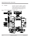
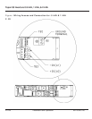

For optimum inverter performance, provide ventilation
clearance from exterior surfaces as follows:
Top and bottom: 0.25 inches [6.3 mm]
Front and sides: 1.50 inches [38.1 mm]
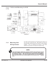
• Verify the inverter module is NOT installed into its
receiver cabinet.
• After the receiver cabinet has been wired, verify that a
separate grounding electrode has been connected to
the chassis "GROUND" lug.
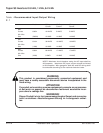
• Turn on the Utility AC and verify the proper AC voltage
exists at ACIN "L" with respect ACIN "N" and chassis
"GROUND".
• Turn on the DC supply to the unit.
• Verify polarity of the DC voltage, positive on "+DC" and
negative on "-DC".
• Turn OFF all AC and DC power to the receiver cabinet.
• The Inverter module is delivered from the factory set for
120 VAC, 60 Hz , auto-restart, ON LINE (Inverter) mode
operation.
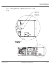
• See Figure 1-3 and perform the following steps for a
personalized inverter set up.
2.6 Inverter Set UP
2.5.5 Cooling
WARNING
AC output will be present at the output terminals immediately when AC
input is energized even without the inverter module installed in the
receiver cabinet.
ATTENTION
La tension alternative de sortie appara ît dès la mise sous tension de
le'entrée, même si le module onduleur n'est pas installé.
WARNUNG!
Die Netzausgangsspannung ist unmittelbar an den Ausgangsklemmen,
sowie der Netzeingang angeschlossen wird-slebst wenn der Einschub
nicht im Gestell ist.
86-153061-00 2 — 9Installation and Operation
Owner’s Manual