The battery booster is a "continuous" mode Fly-back
converter which takes the DC input voltage and boost it to
four separate outputs of 200 volts. Two of these outputs are
connected in series to produce -200 VDC and +200 VDC and
used by one of the Inverters. The other two outputs are also
connected in series to produce a second -200 and +200 VDC
to be used by the second Inverter. The booster transformer,
which is actually a coupled inductor, is used to isolate the
primary DC input from the two +/-200 VDC outputs used to
generate the two AC outputs. The total DC bus voltage (+/-
200 volts) of one inverter is regulated. Feedback is provided
through an analogue optical coupler to control a hysteretic
current mode switch.
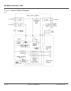
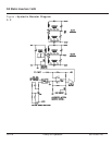
Figure 3-2 shows the basic concept of the booster. The
voltage error amplifier (TL431) measures the +/-200 VDC
bus (400 volts total) of one of the Inverters and provides an
error signal (via an optical coupler) to a comparator. If the +/-
200 volt bus is lower than normal, the voltage applied to the
positive input of the comparator will become higher, a
demand for more current. A "DC" current transformer
measures the current in the primary and secondaries of the
"coupled inductor". The output of the DC current transformer
is applied to the negative input of the comparator. When the
inductors current has reached the required level, as
measured by the DC current transformer, the comparator
turns OFF, thus turning the Boost switch OFF. Now the
energy stored in the coupled inductor is transferred to the
output energy storage capacitors of the four 200 volt outputs.
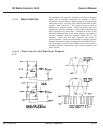
Since the turns ratio of the coupled inductor (transformer) is
1:1:1:1:1, all four DC outputs will be at the same voltage. A
resistor placed between the positive input and output of the
comparator controls the hysteresis level. The hysteresis
current is set at 7.5 A. When the measured current falls
below the hysteresis level applied to the positive input of the
comparator, the comparator turns back ON, which turns ON
the boost switch. Now the cycle starts all over again. The
operating frequency of the battery booster is a function of
input and output voltage, ranging between 20 kHz to 35 kHz.
Since the booster switch (parallel FET) turns ON before the
current in the output secondaries of the transformer goes to
zero, the primary current starts at some level set by the
hysteresis level. This is called a "CONTINUOUS" mode
Flyback converter.
3.1.1.1 Hysteretic Booster
Operation
3.1.1 Battery Booster
86-153061-00 3 — 3Theory of Operation
Owner’s Manual


