When all selections have been made, perform the following
steps to operate the inverter:
A) Be sure that all loads are disconnected or turned OFF
and AC input power to models with a Static Transfer
Switch is OFF.
B) Refer to the installation checklist in Table 2-1 (page
4-3)and be sure that all control settings and terminal
block screws are tight.
C) Check again to see that the DC voltage on the inverter
identification label matches the voltage of your power
source.
D) Set the DC input breaker located on the front panel of
the Inverter module to the OFF position.
E) Install the inverter module into its receiver cabinet and
tighten the two thumb screws.
F) Apply a DC voltage to the DC input terminals.
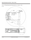
G) Again, using a voltmeter or polarity tester, verify the
voltage at the DC input terminals, positive on +DC (40)
and negative on -DC (41).
H) Turn ON the DC circuit breaker. Within less than a
second, a relay will energize which should be audible.
Then the "STATUS" indicators will sequence through
their RED, YELLOW, GREEN lamp test sequence. The
alarm relays will also be cycling through various states
as the lamp test is progressing. As the battery booster
starts, a "chirp" sound may emanate from the unit. The
Inverter will start, producing the appropriate
voltage/frequency on the ACOUT terminal block, TB3.
The "STATUS" indicator for the "INVERTER" should be
illuminated Green. Verify the proper output voltage with
a voltmeter at TB3. The "STATUS" indicator "BYPASS"
should be RED, blinking ON and OFF at a 1 second
rate.
I) Turn On the Utility AC and verify the "STATUS" indicator
identified as "BYPASS" turns GREEN and continues to
blink ON and OFF at a 1 second rate, indicating the
Inverter is powering the AC output. If BYPASS indicator
is a steady GREEN color, the "INVERTER" LED should
be GREEN, blinking ON and OFF, indicating that the
Utility is powering the AC output. The mode was
selected in paragraph 2.6.4.
J) Units with the DIGITAL LCD option. Scroll through the
readout menu using the SCROLL push-button and
verify the DC input, AC input if applicable, and AC
output voltages agree with the voltmeter readings
previously taken.
2.7 Operation
86-153061-00 2 — 11
Owner’s Manual


