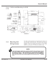
Remove the cover plate on the rear of the inverter receiver
cabinet to gain access to the wiring compartment.
Route the DC input, AC output, AC input (Static Transfer
Switch option), and alarm signal wires through the selected
knockout holes, using the appropriate conduit bushings. Use
knockout cutters to obtain the proper conduit/bushing sizes.
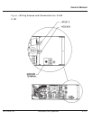
Be sure that the DC input conductors are connected
POSITIVE to the +DC terminal (40) and the NEGATIVE to
the -DC terminal (41).
Before connecting the AC output wires or AC input wires
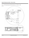
(optional), the ALARM wires should be connected to TB2.
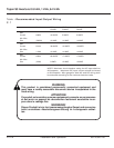
Refer to Figure 1-2 for proper wiring. Alarm relays are shown
in their "ALARM", de-energized position. MAJOR alarm (no
power to the load) terminals are TB2-7 to TB2-12. MINOR
alarm (Inverter Stopped) terminals are TB2-4 to TB2-6.
Utility failure (if Static Transfer Switch option is installed)
terminals are TB2-1 to TB2-3.
AC output is on terminal block TB3, marked "AC OUT".
Make sure the white NEUTRAL wire is connected to AC OUT
"N" and the LINE or HOT wire is connected to AC OUT "L".
If a Static Transfer Switch option is installed, connect the
Utility AC input to terminal block TB3, marked "AC IN".
Again make sure the white NEUTRAL wire is connected to
AC IN "N" and the LINE or HOT wire is connected to AC IN
"L" terminal.
2.5.4.5 AC Hard Wire
Connection
2.5.4.4 Alarm Hard Wire
Connection
NOTE
This inverter was designed with the intent that the user will terminate
the positive polarity terminal of the DC source to earth or chassis
ground. For a positive or floating DC input consult MGE
Customer Support Services.
2.5.4.3 DC Hard Wire
Connection
2.5.4.2 Knockout Access
2.5.4.1 Hard Wire Access
2 — 8 Installation and Operation 86-153061-00
Topaz S3 Inverters 0.5 kVA, 1 kVA, & 2 kVA


