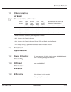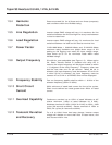
Section Description Page
3.1.3.1.1 Static Transfer Switch 3-7
3.1.3.1.2 Start Up Sequence 3-8
3.1.3.2 Off-Line Mode 3-8
3.1.4 Digital LCD 3-8
3.1.5 Status Indicators (LEDs) 3-8
3.1.5.1 "Bypass" 3-9
3.1.5.2 "Inverter" 3-9
3.1.6 Power Supply 3-9
3.1.6.1 Supply Description 3-9
3.1.6.2 Supply Operation 3-10
Section IV— Maintenance and Service
4.0 . . . . . . . . . . . . . . . Scope 4-1
4.1 . . . . . . . . . . . . . . . Safety Instructions 4-1
4.2 . . . . . . . . . . . . . . . Preventive Maintenance 4-1
4.3 . . . . . . . . . . . . . . . Replacement Parts 4-2
4.4 . . . . . . . . . . . . . . . Troubleshooting and MGE Servicing 4-2
4.4.1 Installation Checks 4-3
4.4.2 Basic Inverter System (-92 Models) 4-4
4.4.3 Inverter With static Transfer Switch
(-94 Models) 4-5
4.4.4 ON-LINE Mode 4-6
4.4.5 OFF-LINE Mode 4-6
4.4.6 Troubleshooting Guide 4-6
Glossary g-1
Illustrations
figure description page
1-1 System Status Readout 1-5
1-1A Line 1 Measurement Readout 1-7
1-1B Line 2 Measurement Readout 1-7
1-1C Line 1 and 2 Measurement Readout 1-8
1-2 Remote Alarm Connection Diagram 1-9
1-3A Inverter Module Configuration
for .5 kVA & 1 kVA 1-12
1-3B Inverter Module Configuration
for 2 kVA 1-13
2-1A Outline and Mounting
for .5 kVA & 1 kVA 2-2
2-1B Outline and Mounting
for .2 kVA 2-3
2-2A Wiring Access and Connection
for .5 kVA & 1 kVA 2-6
2-2B Wiring Access and Connection
for .5 kVA & 1 kVA 2-7
86-153061-00 ix
Owner’s Manual


