


10 - 6 10 - 6
MELSEC-Q
10 TROUBLESHOOTING
10.1.2 Initializing error information of the serial communication module
This section explains the ERR. LED ON factors and the error code initialization (clear)
for the Q series C24.
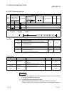
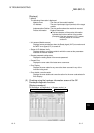
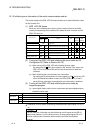
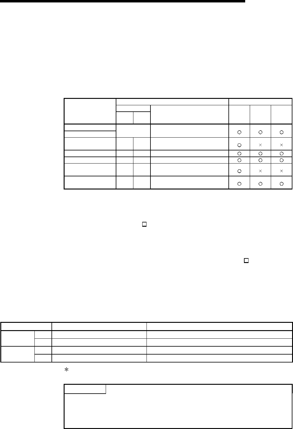
(1) ERR. LED ON factors
When any of the following errors occurs, its error code is stored in the buffer
memory corresponding to the interface (CH) where the error occurred, and the
ERR. LED turns on.
Error code storage buffer memory Applicable protocol
Address
Cause of error
CH1 CH2
Name MC
Non-
procedure
protocol
Bidirec-
tional
protocol
Switch setting error
Mode switching error
203
H
Switch setting error, mode switching error
storage area
On-demand execution
error
256
H
266
H
On-demand execution result storage area
Data transmission error 257
H
267
H
Data transmission result storage area
Data reception error 258
H
268
H
Data reception result storage area
MC protocol transmission
error
025A
H 026AH MC protocol transmission error code
Monitoring device error 2205H 2305H
PLC CPU monitoring function execution
result
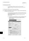
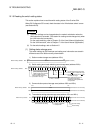
(2) Turning off the ERR. LED and initializing the error codes by GX
Configurator-SC (Refer to Section 8.6.10)
(a) When turning off the ERR. LED and initializing the error codes
By making the CH
ERR. clear request on the "Monitor/Test" screen, the
ERR. LED of the Q series C24 turns off and the stored error codes are
initialized.
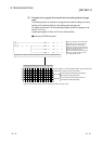
(b) When initializing the communication error information
By making the Communication error clear request for CH
and to turn LED
off on the "Monitor/test others" screen, the LEDs (ERR., NEU.) of the Q
series C24 turn off and the communication error information is initialized.
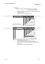
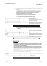
(3) Turning off the ERR. LED and initializing the error codes by
sequence program
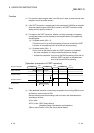
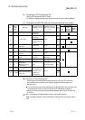
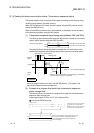
(a) Input signals used to notify of error occurrences and output signals used to
initialize the error code
I/O signal Name of status information Description/function
XE Error occurrence on CH1 side Turns on upon error occurrence in CH1 interface.
Input signal
XF Error occurrence on CH2 side Turns on upon error occurrence in CH2 interface.
YE CH1 Error information initialization request Turns on when initializing error code of interface on CH1 side.
Output signal
YF CH2 Error information initialization request Turns on when initializing error code of interface on CH2 side.
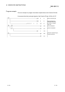
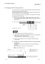
Initialization of error code is continuously performed when output signal (YE/YF) is
on.
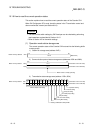
POINT
The CHn side error information can be initialized by an off request to the LED off
request area (address 1
H
) of the buffer memory. By using output signals YE to YF,
the error codes stored in the above buffer memory can further be initialized
(cleared).