


3 - 3 3 - 3
MELSEC-Q
3 SPECIFICATIONS
3.2 RS-232 Interface Specification
The following shows the RS-232 interface specifications.
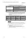
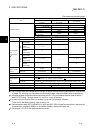
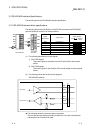
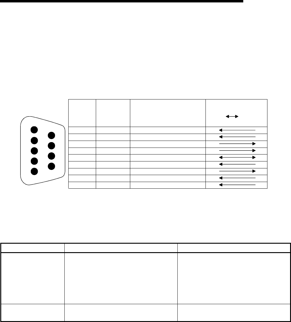
3.2.1 RS-232 connector specifications
The following shows the specifications of the RS-232 connector that connects the Q
series C24 to an external device.
Carrier detect
Receive data
Send data
Data terminal ready
Signal ground
Request to send
Clear to send
CD
RD(RXD)
SD(TXD)
DTR(ER)
SG
DSR(DR)
RS(RTS)
CS(CTS)
RI(CI)
Pin number
Signal name
Signal direction
External
device
1
2
3
4
5
6
7
8
9
C24
9
1
2
3
4
5
6
7
8
Signal
abbreviation
Call Indicate
Dataset ready
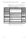
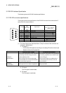
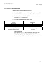
(1) The control signals are described below. (The pin numbers of the connector are
enclosed in parentheses.)
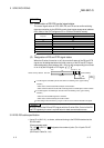
1) CD signal (1)
• The Q series C24 operates according to the setting CD terminal check (see
Section 8.4.5) of the Q series C24.
CD terminal check enabled CD terminal check disabled
Full-duplex
communication
• The Q series C24 performs send and receive
processing when the CD signal (receive
carrier detection) is ON.
• If the CD signal is turned off during data
communication, the Q series C24 initializes
the transmission sequence.
• The Q series C24 performs send and receive
processing regardless of the ON/OFF status
of the CD signal.
• Data communications is possible with an
external device that cannot turn the CD
signal ON/OFF.
Half-duplex
communication
See Chapter 8 of User's Manual (Application) Setting impossible.
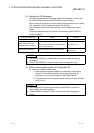
2) RD signal
This is a signal to receive data.
3) SD signal
This is a signal to send data.