


4 - 9 4 - 9
MELSEC-Q
4 SETTINGS AND PROCEDURES PRIOR TO OPERATION
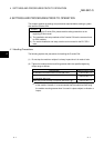
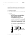
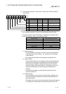
(c) Terminal resistor must be set (or connected) for the station of both ends on
the circuit.
Match the Q series C24 to the specifications of the external device and
connect a terminal resistor (packed with the Q series C24) according to this
section.
Connect, or set a terminal resistor at the external device according to the
instruction manual of the external device.
(The terminal resistor to connect to the Q series C24)
• When communications performed using RS-422, "330
1/4 W" resistor is
connected.
• When communications performed using RS-485, "110
1/2 W" resistor is
connected.
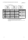
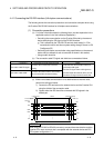
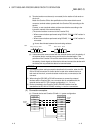
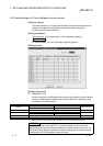
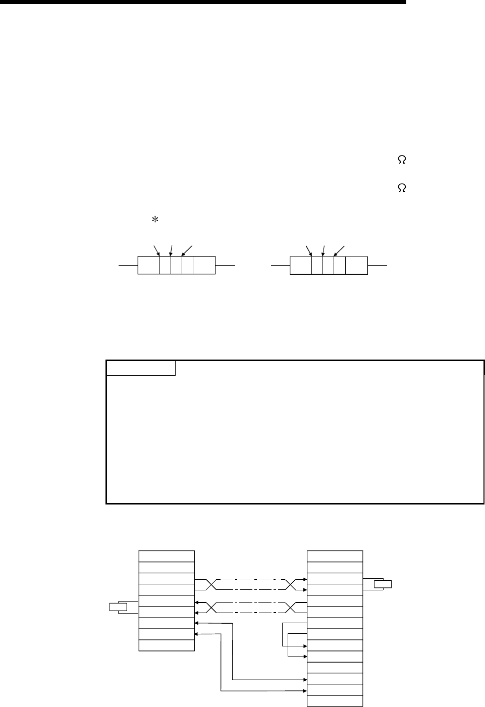
How to discriminate between the terminating resistors
330
Ω
110
Ω
Brown
Orange
Orange
Brown Brown Brown
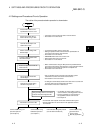
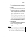
(d) If data cannot be communicated with the external device at all, the polarity of
the external device could be wrong and should be checked again. If the
polarities of the Q series C24 and the external device do not match, reverse
the polarity of each signal on either device side and connect the devices with
the cable; this may enable the data to be communicated.
POINT
(1) For terminal resistor setting/connection described in this section, when the RS-
232 to RS-422 converters or similar device is used at the external device at
both ends of the circuit, a terminal resistor must be set, or connected, at the
converter.
(2) When using the RS-232C to RS-422 converters to connect the external
devices and the Q series C24, use a converter that is compatible with the
external device and PLC CPU system configuration (1:1, 1:n, m:n).
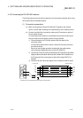
(3) Device connected to the Q series C24 RS-422/485 interface must be
standardized as RS-422 or RS-485, including 1:n and m:n connections.
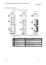
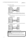
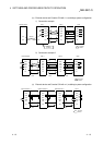
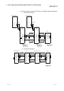
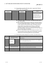
(2) Connection examples
(a) External device and Q series C24 with 1:1 system configuration
Terminal
resistor
R
R
Q series C24
Signal name
SDA
SDB
RDA
RDB
External device
RDA
RDB
SDA
SDB
RSA
RSB
CSA
CSB
SG
FG
SG
FG
FG
Terminal
resistor
Signal name