


4 - 5 4 - 5
MELSEC-Q
4 SETTINGS AND PROCEDURES PRIOR TO OPERATION
4.4 External Wiring
This section explains wiring between the Q series C24 and external device.
As the wiring precautions, external wiring which is resistant to the effects of external
noise is a prerequisite for reliable system operation and full use of the Q series C24
function.
(1) Ground the shield at only one point.
(2) When connecting with an external device using an RS-232 line, use a connector
shell as specified in Section 3.2.1 on the Q series C24 end.
(3) When connecting with an external device using an RS-422/485 cable, be sure to
note the following.
(a) QJ71C24N and QJ71C24
1) Use the RS-422/485 cable recommended in section 3.3.2.
2) The RS-422/485 interface terminal block uses M3 terminal screws.
Use suitable crimp-on terminals for the terminals.
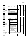
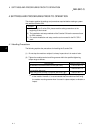
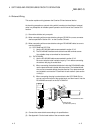
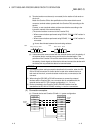
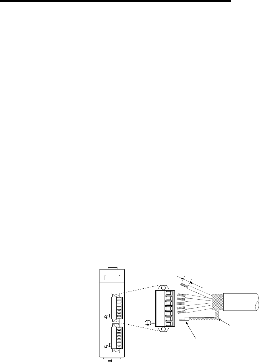
(b) QJ71C24N-R4
1) Use the RS-422/485 cable recommended in section 3.3.2.
Be sure to strip the outer insulation layer by 7 mm before connecting
the cable to the plug-in socket block.
2) When connecting the braided shield wire inside the RS-422/485 cable,
use the plate terminals included with the product. The braided shield
wire can be connected without the plate terminal. Four plate terminals
are included to connect the FG terminals of both stations. (see section
4.4.2.(6).)
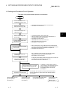
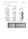
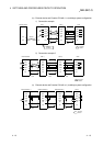
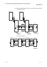
3) When connecting the plug-in socket block to the QJ71C24N-R4, be
sure to confirm the layout of the socket block, and then insert it into the
RS-422/485 connector on the QJ71C24N-R4.
SG
RDB
RDA
SDB
SDA
(FG)
Plate terminal
(included with product)
Braided shield wire
7
mm
(0.28 in.)
CH2
CH1
RS-422/485
RS-422/485
QJ71C24N-R4
(FG)
SG
RDB
RDA
SDB
SG
RDB
RDA
SDB
SDA
SDA
(FG)
QJ71C24N-R4
RUN
RD
NEU.
SD
NEU.
RD
SD
CH1
CH2
ERR.
(4) Connect the external device according to its specifications.
(5) See Appendix 5 for the bend radius of the connection cable.