


App. - 54 App. - 54
MELSEC-Q
APPENDIX
Appendix 9.12 When changing the communication protocol and transmission setting
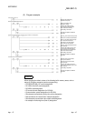
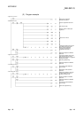
This section provides a program example that changes the communication protocol
and transmission setting using the REMFR/REMTO instructions and I/O signals.
(When the module is used on a MELSECNET/H remote I/O station, the station No.
cannot be changed because the UINI instruction is unavailable.)
For changing the communication protocol and transmission setting, refer to Chapter 15
of the User's Manual (Application).
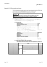
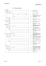
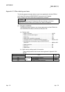
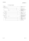
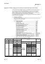
(1) Program conditions
When the change command (X1031) turns on, the communication protocol and
transmission setting are changed.
(a) Devices used by user
• Change command .................................................................. X1031
• Changing flag.......................................................................... M300
• Change completion flag.......................................................... M301
• CH1 change command pulse signal ...................................... M10
• CH1 change command........................................................... M11
• CH1 mode switching completion............................................ M12
• CH1 receive processing.......................................................... M13
• CH1 send processing ............................................................. M14
• CH2 change command pulse signal ...................................... M20
• CH2 change command........................................................... M21
• CH2 mode switching completion............................................ M22
• CH2 receive processing.......................................................... M23
• CH2 send processing ............................................................. M24
• REMFR/REMTO instruction completion device..................... M100 to 107
• REMFR/REMTO instruction abnormal completion flag......... M200 to 205
• Switching mode No. designation............................................ D0, D10
• Transmission specifications after switching designation....... D1, D11
• Switch setting error and mode switching error status............ D2, D12
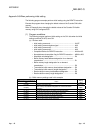
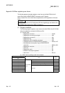
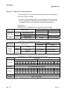
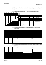
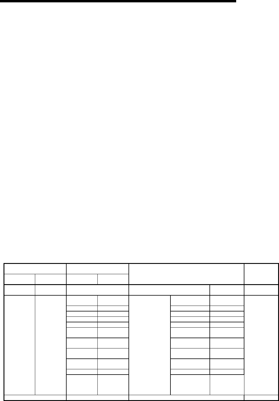
(b) Buffer memory settings used in this example
Address, Decimal
(Hexadecimal)
Bit
CH1 CH2 Position
Specified
value
Description Set value
114 (90
H
) 304 (130
H
) — Switching mode No. designation
MC protocol
(Format 1)
0001
H
b0 OFF
Operation
setting
Independent
b1 OFF Data bit 7 bits
b2 OFF Parity bit No
b3 OFF Even/odd parity Odd
b4 ON Stop bit 2 bits
b5 ON
Sum check
code
Yes
b6 OFF
Write during
RUN
Prohibited
b7 ON
Setting
modifications
Allowed
b8 to b11 —
Communication
rate setting
9600bps
B12 to 14 All OFF For system —
145 (91
H
) 305 (131
H
)
B15 ON
Transmission
specifications
after switching
designation
Transmission
specifications
after switching
designation
Make setting
as set in this
area.
85B0
H
515 (203
H
) — Switch setting error and mode switching error status —