


4 - 7 4 - 7
MELSEC-Q
4 SETTINGS AND PROCEDURES PRIOR TO OPERATION
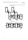
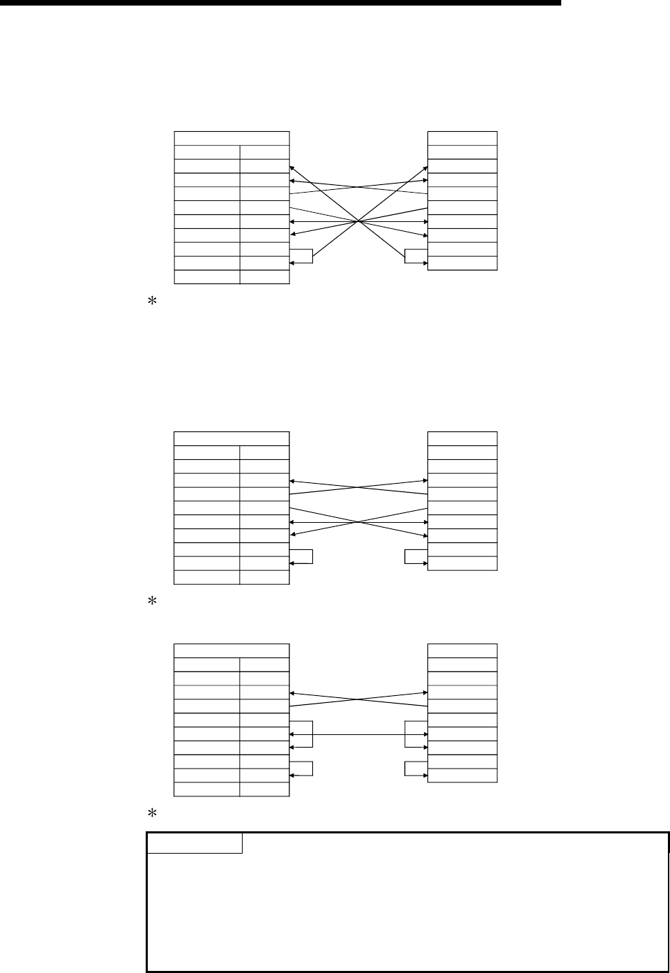
(2) Connection examples
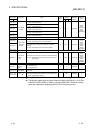
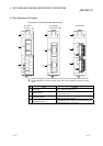
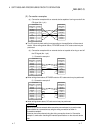
(a) Connection example with an external device capable of turning on and off the
CD signal (No. 1 pin)
Q series C24
Pin No.
CD
RD(RXD)
SG
DSR(DR)
1
2
3
4
5
6
7
8
9
External device
Signal name Signal name
SD(TXD)
DTR(ER)
RS(RTS)
CS(CTS)
RI(CI)
CD
RD(RXD)
SG
DSR(DR)
SD(TXD)
DTR(ER)
RS(RTS)
CS(CTS)
The CD terminal check setting is set according to the specification of the external
device. When wiring shown above, DTR/DSR control or DC code control may be
performed.
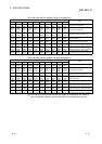
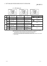
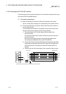
(b) Connection example with an external device not capable of turning on and off
the CD signal (No. 1 pin)
1) Connection example 1
Q series C24
Pin No.
CD
RD(RXD)
SG
DSR(DR)
1
2
3
4
5
6
7
8
9
External device
Signal name
Signal name
SD(TXD)
DTR(ER)
RS(RTS)
CS(CTS)
RI(CI)
CD
RD(RXD)
SG
DSR(DR)
SD(TXD)
DTR(ER)
RS(RTS)
CS(CTS)
When wiring shown above, DTR/DSR control or DC code control may be performed.
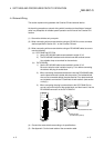
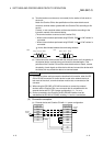
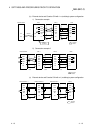
2) Connection example 2
Q series C24
Pin No.
CD
RD(RXD)
SG
DSR(DR)
1
2
3
4
5
6
7
8
9
External device
Signal name
Signal name
SD(TXD)
DTR(ER)
RS(RTS)
CS(CTS)
RI(CI)
CD
RD(RXD)
SG
DSR(DR)
SD(TXD)
DTR(ER)
RS(RTS)
CS(CTS)
When wiring shown above, DC code control may be performed.
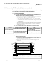
POINT
If the PLC CPU and an external device cannot be communicated, try to perform data
communication as a connection test, using the wiring connection as shown in
Connection example 2.
If data can be communicated using the wiring connection shown in Connection
example 2, rewire after checking the interface specifications on the external device
side.