


10 - 8 10 - 8
MELSEC-Q
10 TROUBLESHOOTING
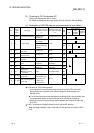
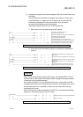
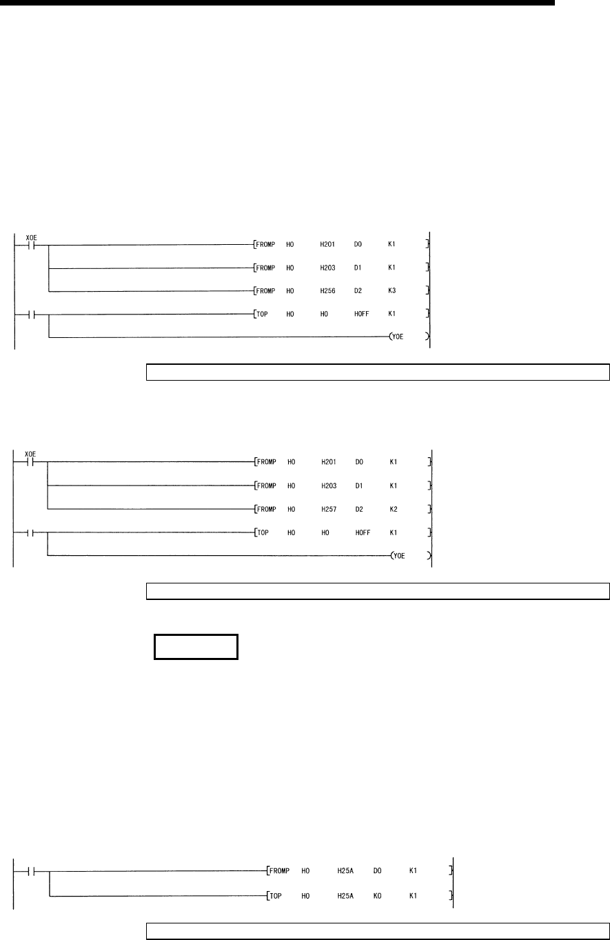
(c) Examples of programs that initialize displayed LED and communication error
information
The following shows examples of a program that reads error codes when
errors described in (1) above occur in an interface on the CH1 side and
initializes the displayed LED and communication error information.
Incorporate the necessary part of the program.
(Input/output signals X/Y00 to X/Y1F of the Q series C24)
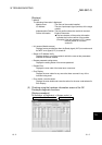
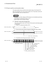
1) When data is communicated using the MC protocol
Turn off/clear
command
Reads LED and communication error
information from address 201
H
.
Reads switch setting error description from address 203
H
.
Reads data transmission/reception
results from address 256
H
to 258
H
.
Requests initialization of error information on the
CH1 side and clearing of error codes in the buffer memory.
Requests initialization of error information on the CH1
side and clearing of error codes in the buffer memory.
Check the error codes and take corrective action according to Section 10.2.
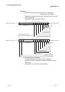
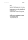
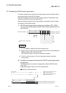
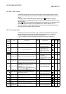
2) When data is communicated using the non procedure or bidirectional
protocol
Reads LED and communication error information from
address 201
H
.
Reads switch setting error description from address 203
H
.
Reads data transmission/reception results from address
257
H
to 258
H
.
Writes initialization request such as for displayed LED to
address 0
H
.
Requests initialization of error information on the CH1
side and clearing of error codes in the buffer memory.
Turn off/clear
command
Check the error codes and take corrective action according to Section 10.2.
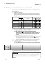
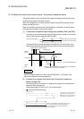
REMARK
When data is communicated using the MC protocol, the displayed ERR. LED may
not be turned on if the Q series C24 sends an NAK message to the external device
in response to the command message.
Error codes (see Section 10.2) corresponding to the error content when the NAK
message is sent back to the external device are stored in the following areas. (when
communicating with an A compatible 1C frame, the error codes differ from the
transmission error code.)
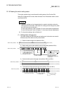
When checking error codes transmitted by the PLC CPU, incorporate the following
program (in case of the interface on the CH1 side).
Read command
Reads transmission error codes from address 25A
H
.
Clears error codes.
Check the error codes and take corrective action according to Section 10.2.