


PH50, XL50, XL21 series Set-up and Installation Manual
20
A
nchor bolts
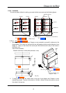
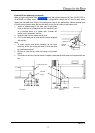
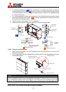
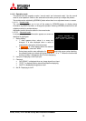
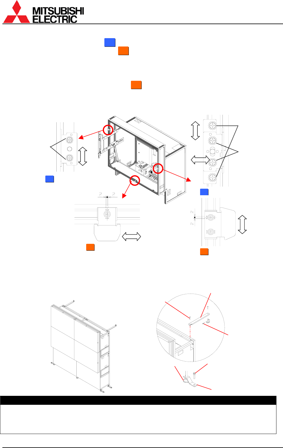
3. For horizontal adjustment:
5
5
0
0
”
”: Loosen two screws in the right screen guide to adjust its
horizontal position and fix them.
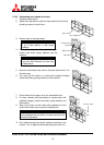
6
6
7
7
”
”: Loosen the screw in the bottom screen guide to adjust
its horizontal position and fix it. The screen guide has punch marks at the adjustable range
(+/- 2mm) and its center.
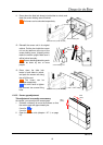
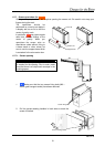
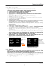
4. For vertical adjustment: Loosen two screws each in the left and right screen guides to adjust
their vertical positions and fix them.
6
6
7
7
”
”: The screen guides have the punch marks at the
same position as described above.
5. Close the screen units (chapter 1.2.7.2, on page 22).
6. Check the screen gaps and repeat the steps until you get reasonable gaps.
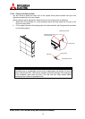
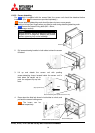
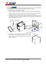
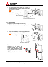
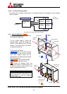
1.2.6.6. Fixing to the wall and floor
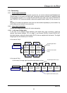
1. Attach floor-fixing brackets on 4 level adjusters below the base stand and fix them to the
floor with anchor bolts.
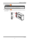
2. Fix the upper back part of the display wall to the back wall with wall-fixing brackets as shown
in the following figure.
Caution
Make sure the whole set is assembled firmly and installed stably. To prevent the set from falling
due to unpredictable events such as earthquakes and shocks, fix the set firmly to the wall and
floor. Furthermore, carefully confirm the strength of the fixing area of the installation place (wall
and floor). The wall and floor fixing method differs according to the number of the assembled units.
A
djusters
A
nchor bolts
Wall-fixing brackets
Floor-fixing brackets
Hexagon socket head
cap screws (M6)
5
5
0
0
”
” Left screen guide
For horizontal
adjustment
For vertical
adjustment
For vertical
adjustment
6
6
7
7
”
” Bottom screen guide
6
6
7
7
”
” Screen guide (both side)
5
5
0
0
”
” Right screen guide
For vertical
adjustment
For horizontal
adjustment