


REV 2.4
93
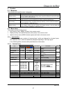
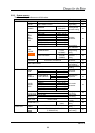
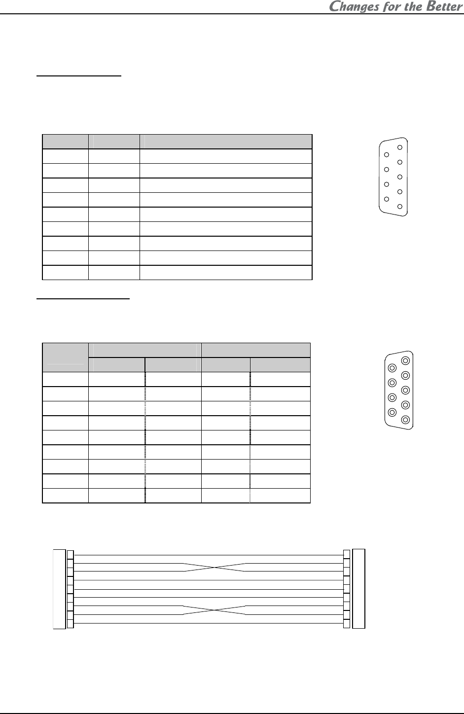
3.6. Terminal functions
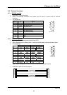
3.6.1. RS-232C terminal
• Connector: D-sub 9 pins male
• Cable: Commercially available cross cables can be used to connect with an external
controller.
• Pin assignment:
Pin No. I/O Signal
1 – N.C.
2 Input RD (Receive Data)
3 Output SD (Send Data)
4 Output ER (Equipment Ready)
5 – SG (Signal Ground)
6 Input DR (Data Set Ready)
7 – N.C.
8 – N.C.
9 – N.C.
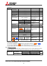
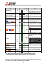
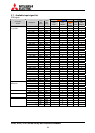
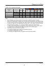
3.6.2. CONTROL terminal
• Connector: D-sub 9 pins female (both IN and OUT)
• Cable: Supplied control cables (male – male) should be used to connect between cubes.
• Pin assignment:
I/O Signal
Pin No.
IN OUT IN OUT
1 Input Output EXVIN EXVOUT
2 Output Output TXDS2 TXDM2
3 Input Input RXDS2 RXDM2
4 Output Input GND GND
5 Input/output Input/output UP/BUSY UP/BUSY
6 Input Output RCIN RCOUT
7 Output Output TXDS2 TXDM2
8 Input Input RXDS2 RXDM2
9 Output NC DE1 NC
Note: The pin assignment is different from conventional models (FD series).
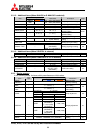
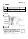
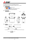
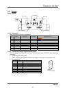
• CONTROL cable connection diagram
8
9
7
6
5
3
4
1
2
7
6
8
9
1
3
2
5
4
CONTROL
IN/OUT port
1
2
3
4
5
6
7
8
9
1
2
3
4
5
6
7
8
9
CONTROL IN
CONTROL OUT
RS-232C port