


10
DataTalker Owner’s Manual
1.3 Product Description
The DataTalker series of multiplexers has a single synchronous or asynchronous data channel, a
command port, one or two voice/fax channels, and a single synchronous composite link with an
internal data service unit (DSU), modem, ISDN terminal adapter, or an external synchronous link
device. The DataTalker can be connected to an asynchronous device such as a PC or host
computer, an external synchronous device such as a LAN router, or the composite link of an
MMH900 series MultiMux. It also can be connected to telephone equipment for voice or fax traffic
over your standard composite link. The DataTalker’s data port allows either synchronous or
asynchronous devices to be connected to it. The command port allows you to configure your data
channel, composite link, and voice mode of operation. The composite link can be configured for
an internal 28.8K bps dial-up/leased line modem, an internal DSU for digital communications over
a digital data service (DDS) network, or an ISDN terminal adapter for Basic Rate Interface
Service. It can also be configured for external synchronous link devices. The voice/fax channel
supports phone, fax, or key telephone system equipment through an FXS interface, a PBX
station-side connection through an FXO interface, or a PBX trunk connection through an E&M
interface. The DT101/V34 and DT102/V34 DataTalkers are dual-function models. If the user
requires traditional data communications, these models provide a simple switch to enable a
standalone V.34 modem mode, which supports dial-in/dial-out data communications for Internet,
BBS, and other on-line access.
Serial
Communications
Controller
PDN
FXS
FXO
Port
RAM
RAM
AT Commands
Analog
to
Digital
Digitize
Voice/fax
Digital
to
Analog
Configurations
Composite
Link
2
3
1
4
5
6
7
9
8
Fax/Telephone
E&M
Trunk
Trunk
Station
Trunk
Station
PBX
PSTN
RAM
EPROM
Digital
Signal
Processor
Channel 1
CODEC
A to D
D to A
Modem,
DSU, or
Terminal
Adapter
L
i
n
k
C
o
m
p
o
s
i
t
e
Data/Command
Processor
EPROM
I/O
Data/
Command
Channel
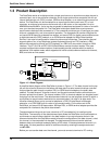
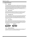
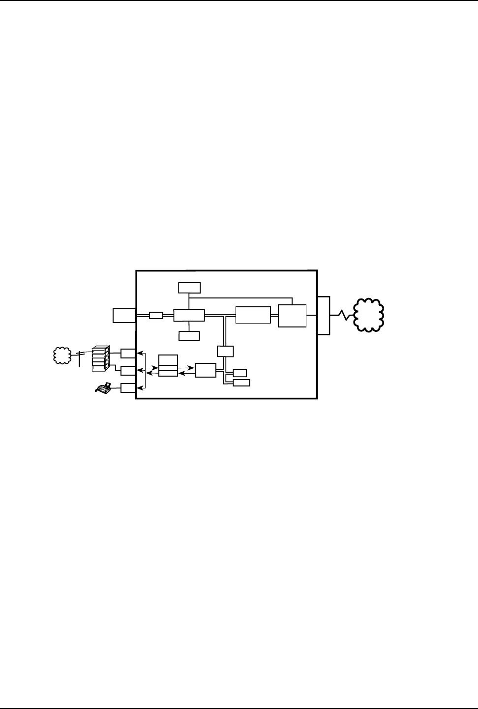
Figure 1-2. Block Diagram
A simplified block diagram of the DataTalker is shown in Figure 1-2. The data channel on the top
left and the voice/fax channel on the bottom left feed data to a serial communications controller
that provides the path through a modem, DSU, or ISDN terminal adapter to the public data
network. The data channel, voice/fax channel, and the serial communications controller are on
the main printed circuit board. The internal modem, DSU, or terminal adapter is a daughter board
that plugs into the main board. The data/command channel is a dual purpose channel to which a
synchronous or asynchronous device can be connected when it is used in its data mode. The
voice/fax channel allows you to connect a telephone, a PBX (Private Branch eXchange)
extension, or a PBX E&M trunk for voice or fax communication. On the other end of the
DataTalker, an internal 33.6K bps modem, 56K bps DSU, or ISDN terminal adapter provides the
composite link interface to the public data network.
The data/command channel can have a terminal or PC connected to it for configuring the
DataTalker. The versatility of the data/command port allows the DataTalker to be connected to a
synchronous or asynchronous device in the data mode or to an asynchronous device in the
command mode when the DataTalker needs to have the configuration of the data channel, voice/
fax channel, or the composite link changed. The data/command channel can be switched
between data and command modes by setting a DIP switch. If the data/command channel is in
data mode, it is also possible to switch to command mode by entering the escape command
+++AT<CR>.
Before you can transfer data over the channel, you must connect a terminal or PC running